


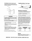
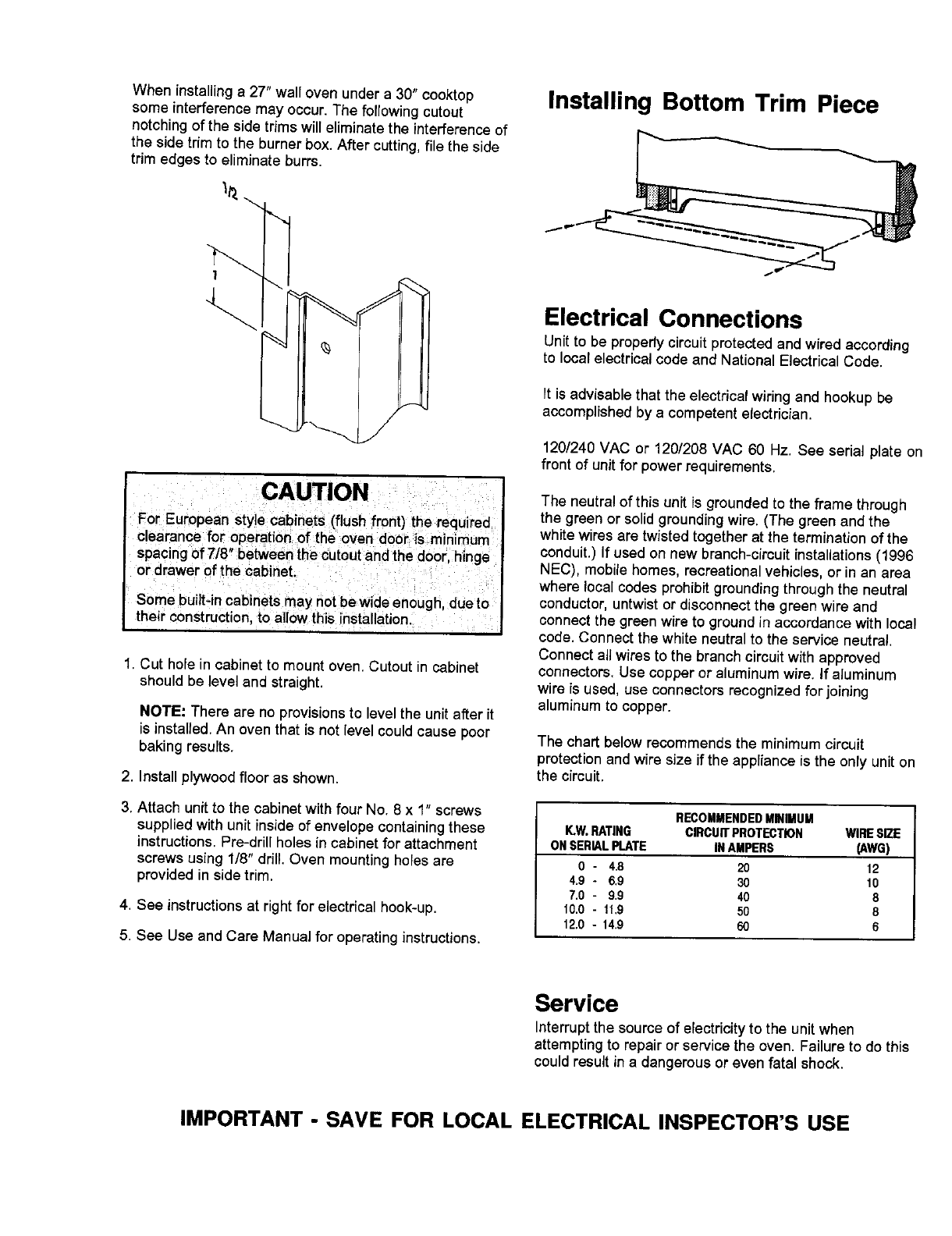
When installinga 27" wall oven under a 30" cooktop Installing Bottom Trim Piece
some interferencemay occur.The followingcutout
notching of the side trims will eliminate the interference of
the side trim to the burner box. After cutting, file the side
trim edges to eliminate burrs.
_" _-'-_ 1.,-
f Electrical Connections
' Unit to be propedycircuitprotectedand wiredaccording
_ to local electrical code and National ElectricalCode.
It is advisablethat the electrical wiring and hookup be
accomplished by a competent e(ectrician.
120/240VAC or 120/208 VAC 60 Hz. See serial plate on
front of unit for power requirements.
CAUTION The neutral of this unit is grounded to the frame through
For European style cabinets (flush front) the required the green or solid grounding wire. (The green and the
clearance for operation of the oven door is minimum white wires are twisted together at the termination of the
spacing of 718"between the cutout and the door, hinge conduit.) If used onnew branch-circuit installations (1996
or drawer of the cabinet. NEC), mobile homes, recreational vehicles, or in an area
where local codes prohibit grounding through the neutral
Some built-in cabinets may notbe wide enough, dueto conductor, untwist or disconnect the green wire and
their construction, to allow this installation, connect the green wire to ground in accordance with local
code. Connect the white neutral to the service neutral.
Connect ail wires to the branch circuit with approved
1. Cut hole in cabinet to mount oven. Cutout in cabinet connectors. Use copper or aluminumwire. If aluminum
should be level and straight, wire is used, use connectors recognized for joining
aluminum to copper.
NOTE: There are no provisions to level the unit after it
is installed. An oven that is not level could cause poor The chart below recommends the minimum circuit
baking results, protection and wire size if the appliance is the only unit on
2. Install plywood floor as shown, the circuit.
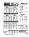
3. Attach unit to the cabinet with four No. 8 x 1" screws RECOMMENDEDMINIMUM
suppliedwith unit inside of envelope containingthese ICW.RATING CIRCUITPROTECTION WIRESIZE
instructions. Pre-drill holes in cabinet for attachment ONSERIALPLATE INAMPERS (AWG)
screws using 1/8" drill. Oven mounting holes are 0 - 4.8 20 12
provided in side trim. 4.9 ° 6.9 30 10
7.0- 9.9 40 8
4. See instructions at right for e_ectficalhook-up. 10.0- 1_9 50 8
12.0- 14.9 60 6
5, See Use andCare Manualfor operatinginstructions,
Service
Interruptthe sourceofelectricityto the unitwhen
attemptingto repairor servicethe oven. Failuretodo this
couldresultin a dangerousoreven fatal shock.
IMPORTANT - SAVE FOR LOCAL ELECTRICAL INSPECTOR'S USE