


2
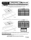
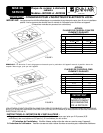
Installing Cabinetry Over Your Cooktop
A= 30²
²²
² (76.2 cm) minimum
clearance between the top of
the cooktop and the bottom of
an unprotected wood or metal
cabinet.
A= 24²
²²
² (60.96 cm) minimum when
bottom o f wood or metal
cabinet is protected by not less
than 1/4² (0.635 cm). FLAME
RETARDANT millboard
covered with not less than no.
28 MSG sheet steel, 0.015²
(0.038 cm) stainless steel, 0.024²
(0.061 cm) aluminum or copper.
* To eliminate the risk of burns or fire by reaching over
heated surface units, cabinet storage space located
above the surface units should be avoided. If cabinet
storage is to be provided, the risk can be reduced by
installing a range hood that projects horizontally a
minimum of 5 inches beyond the bottom of the cabinets.
Important Installation Suggestions
1. Chamfer all exposed edges of decorative laminate to
prevent damage from chipping.
2. Radius corners of cutout and file to insure smooth
edges and prevent corner cracking.
3. Rough edges, inside corners which have not been
rounded and forced fits can contribute to cracking of
the countertop laminate.
4. Countertop must be supported within 3² (7.62 cm) of
cutout.
CAUTION
Warranty is void on equipment installed other than
as recommended by manufacturer.
Electrical Wiring Information
If used on new branch-circuit installations (1996 NEC),
mobile homes, recreational vehicles, or in an a rea where
local codes prohibit grounding through the neutral
conductor, connect the ground wire to ground in
accordance with local code. Connect all wires to the
branch circuit with approved connectors. Use copper or
aluminum wire. If aluminum wire is used, use connectors
recognized for joining aluminum to copper.
CAUTION
This is a two wire with copper ground 208/240 volt
AC appliance. Copper ground is chassis ground
and must be connected to supply ground.
Proper Electrical Supply
You must provide an adequate electrical supply system
as required for your cooktop. All wire connections must be
in accordance with local codes and properly insulated.
Check with local utility for governing electrical codes and
ordinances. In the absence of local electrical codes, the
National Electrical Code, NFPA No. 70, governing electric
range installations must be followed. A copy of the
National Electrical Code, NFPA No. 70, can be obtained
by writing to:
National Fire Protection Association
Batterymarch Park
Quincy, Massachusetts 02269
This is a 2-wire, 240-volt unit. Connect only to a 3-wire,
120/240-volt power supply; the neutral conductor is not
required for the operation of the appliance. The potential
at the power supply electrical connections shall be
150-volts-to-ground or less. The grounding (bare) wire is
connected to the frame of the unit; connect it to a
separate ground. The chart below recommends the
minimum circuit protector and wire size if the appliance is
the only unit on the circuit. If smaller sizes of wire are
used, the unit efficiency will be reduced and a fire hazard
may b e created. It is advisable that the electrical wiring
and hookup be accomplished by a competent electrician.
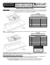
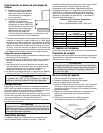
RECOMMENDED MINIMUM
K.W. RATING CIRCUIT PROTECTION WIRE SIZE
ON SERIAL PLATE IN AMPRES (AWG)
0- 4.8 20 12
4.9 - 6.9 30 10
7.0 - 9.9 40 8
10.0 - 11.9 5 0 8
12.0 - 14.9 6 0 6
Notice To Installer
Follow a ccompanying i nstruction carefully.
Preparation Of Countertop
The cutout in the countertop into which the appliance is to
be installed should be prepared according to the cutout
dimensions given on page 1 of these instructions.
CAUTION
Cutout dimensions are critical. Dimensions must
be measured and cut accurately to within +
1/16²
(.16 cm) to insure proper fit.
Installation Of Appliance
1. Remove the cooktop from the carton.
2. Provide cutout in countertop a s required per page 1.
3. Place unit in the cutout.
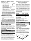
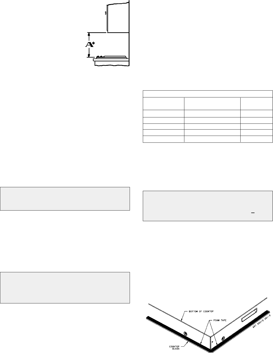
4. Optional - Foam Tape Installation - see illustration
figure 3. Apply foam tape to cook top a s shown in
figure 3 if counter top is not flat.
5. Make electrical wire connection to unit. Consult local
codes for proper power hook-up.
6. Test to insure touch controls operate all elements
properly.
FIGURE 3