


11
5. Complete Steps 5, 8 and 9 on pages 8 & 9 to
complete the installation of natural gas main spuds
in their correct locations.
6. Save the o rifices & chokes removed from the
appliance for future use. They will be needed if this
appliance is again converted for use with LP gas.
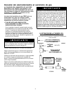
C. INVERT CAP IN APPLIANCE PRESSURE
REGULATOR. (See figure 12).
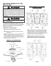
With the appliance installed the appliance regulator
should be located as shown in either figure 3 or figure 4
(pages 4 & 5). Identify the type of appliance regulator
and follow the instructions in the appropriate illustration.
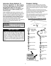
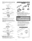
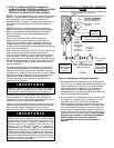
D. RESET THE V ALVES FOR NATURAL GAS
1. Light one burner, and set on low.
2. Remove the knob.
3. Remove the rubber grommets.
4. Locate the valve adjustment screw. See figure 13.
5. Insert a slender, thin-blade screwdriver into knob hole
and engage blade with slot in adjusting screw.
6. Starting from the LP position (see # 5 on page 9, under
C. LOW FLAME ADJUSTMENT), turn the screw
counter clockwise until the flame stabilizes and
matches the pictured “ low” setting on figure 14. Proper
adjustment will produce a stable, steady blue flame of
minimum size. The finaladjustment should be checked
by turning the knob from high to low several t imes
without extinguishing the flame.
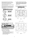
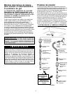
After Steps A, B and C have been completed, check
the appearance of each burner’s flame at the Hi and Lo
settings against figure 14. If the flames appear too
large or too small, make sure all steps were completed
correctly.
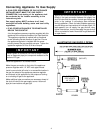
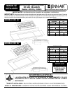
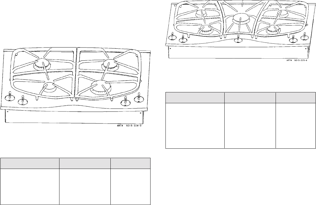
JENN-AIR 30²
²²
²
INPUT RATES - NATURAL GAS / LP GAS (BTU/HR)
FIGURE 17
BURNER LOCATIO N Hi Lo
Right Front 15,000 / 15,000 2000 / 2000
Right Rear 9,200 / 9,100 1450 / 1550
Left Front 5,000 / 4,000 650 / 850
Left Rear 10,500 / 9,100 1450 / 1550
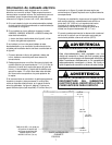
Burner Ignition And
Auto-Reignition
This appliance is equipped for electronic auto-reignition by
means of a spark igniter located at the rear of each
burner. The burners a re designed to light at any valve
rotation that admits sufficient gas flow to support a flame
and to automatically relight following a loss of flame due
to a draft or other adverse condition. This feature is
provided as a convenience and is not intended as a safety
feature.
CAUTION: Nev er cover control knobs or surrounding
control surface with utensils, towels, or other objects.
Never obstruct free air passage past the control knobs.
The knob openings have been sized to p roperly control air
entry to the interior of the appliance during operation.
This appliance has no air shutters. Primary air
adjustments a re unnecessary. The burners are designed
to provide optimum aeration for all gases without air
shutters. When operating properly, burners should
produce clearly defined, even blue flames. If the flames
have yellow tips or are hazy and otherwise appear to
have insufficient air, obtain the s ervices of a qualified
service technician. Some yellow tipping on LP gas is
normal.
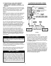
Specified input rates are as shown i n figures 17 and 18.
JENN-AIR 36²
²²
²
INPUT RATES - NATURAL GAS / LP GAS (BTU/HR)
FIGURE 18
5 BURNER MODEL
BURNER LOCATIO N Hi Lo
Right Front 12,500 / 10,500 1450 / 1600
Right Rear 5,000 / 4,000 650 / 850
Left Rear 5,000 / 4,000 650 / 850
Left Front 9,200 / 9,100 1450 / 1550
Center 17,000 / 15,000 2000 / 2000