5
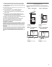
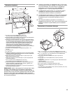
■ Make sure there is a minimum of 18" (45.7 cm) of straight
vent between the elbows if more than one elbow is used.
■ Elbows too close together can cause excess turbulence that
reduces airflow.
■ Do not use a 5" (12.7 cm) elbow in a 6" (15.2 cm) or 3¹⁄₄" x 10"
(8.3 x 25.4 cm) system.
■ Do not reduce to a 5" (12.7 cm) system after using
6" (15.2 cm) or 3¹⁄₄" x 10" (8.3 x 25.4 cm) fittings.
■ Avoid forming handmade crimps. Handmade crimps may
restrict airflow.
■ Use a Jenn-Air
®
vent cap for proper performance. If an
alternate wall or roof cap is used, be certain the cap size is
not reduced and that it has a back draft damper.
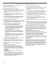
The length of vent system and number of elbows should be kept
to a minimum to provide efficient performance.
The maximum equivalent length of the vent system is 60 ft
(18.3 m). For altitudes above 4,500 ft (1272 m), reduce
recommended vent run by 20% for best performance.
Cold Weather Installations
An additional back draft damper should be installed to minimize
backward cold air flow and a thermal break installed to minimize
conduction of outside temperatures as part of the vent system.
The damper should be on the cold air side of the thermal break.
Makeup Air
Local building codes may require the use of makeup air systems
when using ventilation systems greater than specified CFM of air
movement. The specified CFM varies from locale to locale.
Consult your HVAC professional for specific requirements in your
area.
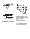
Ve nti ng Me th ods
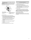
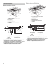
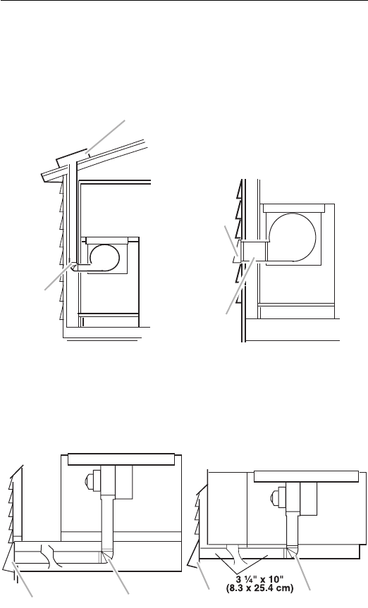
Common venting methods are shown for a counter-mounted
downdraft cooktop. The cooktop may be vented through the wall
or floor.
Option 1 - Roof Venting Option 2 - Wall Venting
A.6" (15.2 cm) round roof
venting
B.Roof cap
A.6" (15.2 cm) round wall
venting
B.Wall cap
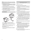
Option 3 - Venting Between
Floor Joist
Option 4 - Venting behind
Cabinet Kick Plate
A.Wall cap
B.6" (15.2 cm) round wall
venting
A.Wall cap
B.6" (15.2 cm) round wall
venting
A
B
A
B
A
B
A
B


