


Published in U.S.A. www.johnsoncontrols.com
VA-9070 Series Electric Rotary Actuators for Two-Position and Modulating Service Installation Instructions2
Metasys® is a registered trademark of Johnson Controls, Inc.
All other marks herein are the marks of their respective owners.
© 2007 Johnson Controls, Inc.
Controls Group
507 E. Michigan Street
Milwaukee, WI 53202
5. With the travel switch in the closed position, rotate
the handwheel one-half turn CW, then turn the
closed travel stop CW until it bottoms out against
the output gear. Lock the travel stop bolts.
Open Travel Switch and Travel Stop
Adjustment
Manually operate the actuator handwheel
Counterclockwise (CCW) until the valve is fully open.
Follow the same procedure as outlined in the Closed
Travel Switch and Travel Stop Adjustment section,
except use the green cam (open) and the travel stop
located on the left side (as seen when viewed from the
travel stop side of the actuator).
Servo Commissioning
Ensure that the travel switches and travel stops are set
properly before calibrating the servo. Use a controlled
and known command signal source. Factory-installed
servos are pre-calibrated.
Setting the Input Control Signal
Set the input control signal for the input type used. See
Table 1.
Setting the Potentiometer
1. Manually operate the actuator handwheel until the
unit is in the fully closed position.
2. Rotate the black potentiometer drive gear
adjustment knob to barely engage the
potentiometer gear segment at the closed position.
3. Manually operate the actuator to the fully open
position.
4. Fine-tune the potentiometer adjustment at this end
to equalize the difference between the ends. The
potentiometer gear segment should maintain
engagement with the drive gear throughout full
actuator travel.
Setting the Servo
1. Wire the input signal to the incoming command
signal terminals. Ensure that you maintain proper
polarity when making wiring connections.
2. Connect the power supply and activate the
actuator.
3. Check the Status Light-Emitting Diode (LED).
• If the red Status LED is flashing, refer to the
Servo Troubleshooting section in the
VA-9070 Series Electric Rotary Actuators
Technical Bulletin (LIT-977325).
• If the green Status LED is flashing, press and
hold the CALIBRATE button until the green
Status LED flashes rapidly (approximately
2 seconds), then release the CALIBRATE
button. The servo drives the valve to the open
and close travel limit switch settings. When the
calibration is complete, the green Status LED
resumes flashing at the normal rate.
• If the Status LED alternately flashes red, then
flashes green, the calibration has failed. To
resolve the problem, refer to the Servo
Troubleshooting section in the VA-9070 Series
Electric Rotary Actuators Technical Bulletin
(LIT-977325).
4. After calibration is complete, apply the desired
minimum and maximum input signals, and observe
the actuator operation through one full cycle for
proper operation.
Repair Information
If the VA-9070 Series Electric Rotary Actuators for
Two-Position and Modulating Service fails to operate
within its specifications, replace the unit. For a
replacement VA-9070 Series actuator, contact the
nearest Johnson Controls® representative.
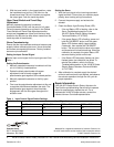
Table 1: Input Control Signal Switch Settings
Switch Input Signal
4 to 20 mA DC 0 to 5 V DC 0 to 10 V DC 2 to 10 V
1 OFF ON ON ON
2 OFF OFF ON ON
3 OFF OFF OFF ON