


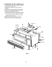
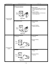
A. PRIMARY INTERLOCK SWITCH TEST
When the door is opened slowly, an audible click
should be heard at the same time or successively
at intervals and the latches should activate the
switches with an audible click.
If the latches do not activate the switches when the
door is closed, the switches should be a adjusted
in accordance with the adjustment procedure.
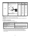
Disconnect the wire lead from the primary switch.
Connect the ohmmeter leads to the common
(COM) and normally open (NO) terminal of the
switch. The meter should indicate an open circuit
in the door open condition.
When the door is closed, the meter should indicate
a closed circuit.
When the primary switch operation is abnormal,
make the necessary adjustment or replace the
switch only with the same type of switch.
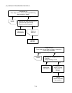
B. SECONDARY INTERLOCK SWITCH TEST
Disconnect the wire lead from the secondary
switch.
Connect the ohmmeter leads to the common
(COM) and normally open (NO) terminals of the
switch. The meter should indicate a open circuit in
the door open condition. When the door is closed,
meter should indicate an closed circuit. When the
secondary switch operation is abnormal, make the
necessary adjustment or replace the switch only
with the same type of switch.
C. MONITOR SWITCH TEST
Disconnect the wire lead from the monitor switch.
Connect the ohmmeter leads to the common
(COM) and normally closed (NC) terminals of the
switch. The meter should indicate closed circuit in
the door open condition. When the door is closed,
meter should indicate an open circuit. When the
monitor switch operation is abnormal, replace with
the same type of switch.
NOTE: After repairing the door or the interlock
system, it is necessary to do this continuity
test before operating the oven.
7-14
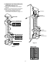
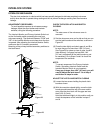
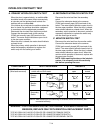
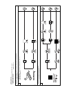
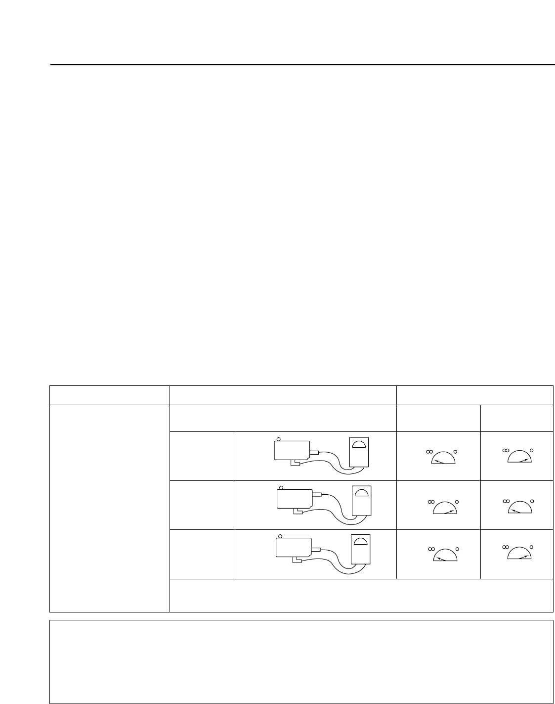
INTERLOCK CONTINUITY TEST
COMPONENTS TEST PROCEDURE RESULTS
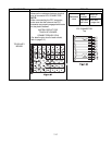
SWITCHES Check for continuity of the Door Door
(Wire leads removed) switch with an Ohm-meter open closed
Primary
Switch
Monitor
Switch
Secondary
Switch
NOTE: After checking for the continuity of switches, make sure that they are
connected correctly.
WARNING : FOR CONTINUED PROTECTION AGAINST EXCESSIVE RADIATION
EMISSION, REPLACE ONLY WITH IDENTICAL REPLACEMENT PARTS.
TYPE NO. SZM-V16-FA-63 OR VP-533A-OF OR V-5230Q FOR PRIMARY SWITCH
TYPE NO. SZM-V16-FA-62 OR VP-532A-OF OR V-5220Q FOR MONITOR SWITCH
TYPE NO. SZM-V16-FA-63 OR VP-533A-OF OR V-5230Q FOR SECONDARY SWITCH
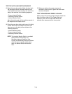
NO
COM
NC
COM
NO
COM