


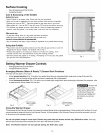
Before Setting Oven Controls
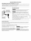
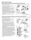
Baking Layer Cakes with 1 or 2 Oven Racks
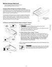
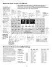
For best results when baking cakes using 2 oven racks, place cookware on oven rack positions 2 & 5 (See Fig. 1 and Fig.
2 on page 9). For best results when using a single oven rack, place cookware on oven rack position 4 (See Fig. 2 and Fig.
2 on page page 9).
Air Circulation in the Oven
For best air circulation and baking
results allow 2-4" (5-10 cm) around
the cookware for proper air circulation
and be sure pans and cookware do not
touch each other, the oven door, sides
or back of the oven cavity. The hot air
must be able to circulate around the
pans and cookware in the oven for
even heat to reach around the food.
Fig. 1 Fig.2
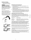
Before Setting Surface Controls
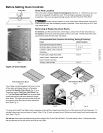
Control Locations of the Gas Surface Burners
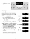
(For models with a Deep Well Cooktop-See Fig. 3)
Ther SIMMER Burner is best used for simmering delicate
sauces, etc. This burner is located at the right rear burner
position on the cooktop.
The STANDARD Burners can be used for most surface
cooking needs. These burners are located at the left front
and center positions on the cooktop.
The POWER Burners are best used for bringing large
quantities of liquid rapidly up to temperature or when
preparing larger quantities of food. These burner are
located at the right front and left rear )ositions on the
cooktop.
2¸¸¸¸¸ •2!i:i::::( ii : :::i::
ii
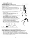
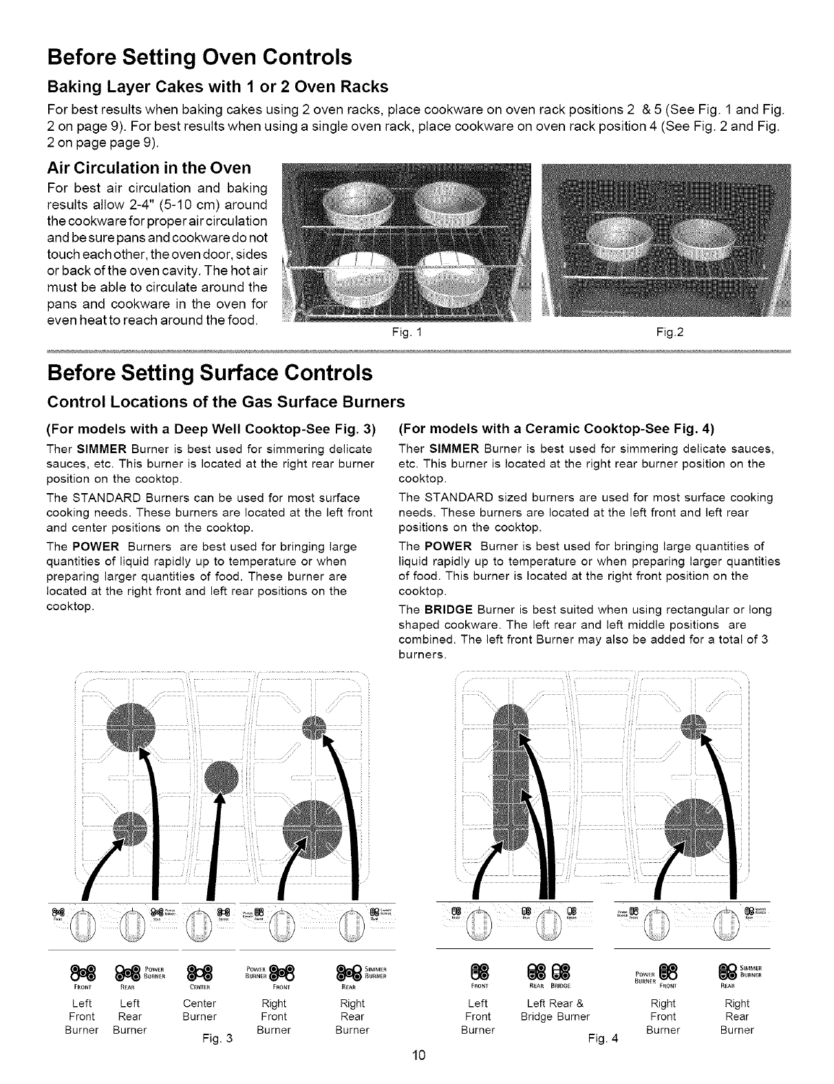
(For models with a Ceramic Cooktop-See Fig. 4)
Ther SIMMER Burner is best used for simmering delicate sauces,
etc. This burner is located at the right rear burner position on the
cooktop.
The STANDARD sized burners are used for most surface cooking
needs. These burners are located at the left front and left rear
positions on the cooktop.
The POWER Burner is best used for bringing large quantities of
liquid rapidly up to temperature or when preparing larger quantities
of food. This burner is located at the right front position on the
cooktop.
The BRIDGE Burner is best suited when using rectangular or long
shaped cookware. The left rear and left middle positions are
combined. The left front Burner may also be added for a total of 3
burners.
i h
i_!!ii!i!
i
FRONT R[AR C_NTER FRONT REAR
Left Left Center Right Right
Front Rear Burner Front Rear
Burner Burner Burner Burner
Fig. 3
88
85
FBONT
Left
Front
Burner
10
88 88 88
REAR BRID6£ FRONI REAl{
Left Rear & Right Right
Bridge Burner Front Rear
Burner Burner
Fig. 4