


I
÷
IMPORTANTSAFETY
INSTRUCTIONS
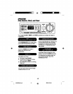
Ard_l-TIp Bracket (contd.)
Step 2
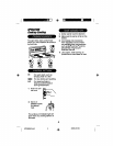
Anti-tip bracket installation
A. Wood Construction:
1. Roor. Drilla _' pilothoaein
the centerofeach pre-.marked
woodfloorholeposition(a nail
or awlmay be usedifa drillis
notavailable),
AND
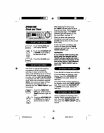
2. Wall: Drillanangled _" pilot
hole (as showninFig.2) inthe
centerofeach pre-marked
wall holeposition(a nailor awl
may be used ifa drillisnot
available).
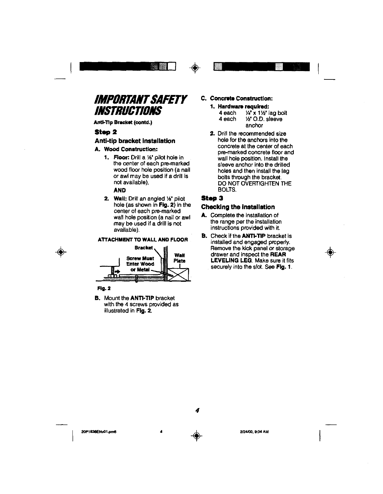
A'rrACHMENTTOWALLANDFLOOR
Bracket
I ScrewMunt "_ Plate
__..._j F.==w_ Im T
Rg. 2
B. Mount theANTI-TIP bracket
withthe4 screwsprovided as
illustratedin Fig. 2,
C. Concrete Construction:
1. Hardware required:
4 each V,'x 11/2'lag bolt
4 each V£O.D. sleeve
anchor
2. Drilltherecommendedsize
hole forthe anchors intothe
concreteat thecenterof each
pre-markedconcretefloorand
wallholeposition.Installthe
sleeveanchorintothedrilled
holesand theninstallthelag
boltsthroughthebracket.
DO NOTOVERTIGHTENTHE
BOLTS.
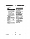
Step 3
Checking the installation
A. Complete theinstallationof
the rangeper theinstallation
instructionsprovidedwithit.
B. CheckiftheANTI.TIP bracketis
installedand engaged properly.
Removethekickpanelor storage
drawerand inspeotthe REAR
LEVEUNG LEG. Makesureitfits
securelyintotheslot.See Fig. 1.
÷
4