


6
6. Fasten shutoff valve to cold water pipe with pipe clamp. Be
sure outlet end is solidly in the ¹⁄₄" drilled hole in the water
pipe and that rubber washer is under the pipe clamp. Tighten
packing nut. Tighten the pipe clamp screws slowly and
evenly so rubber washer makes a watertight seal. Do not
overtighten or you may crush the copper tubing, especially if
soft (coiled) copper tubing is used. Now you are ready to
connect the copper tubing.
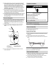
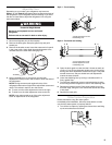
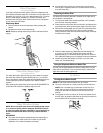
7. Slip compression sleeve and compression nut on copper
tubing as shown. Insert end of tubing into outlet end squarely
as far as it will go. Screw compression nut onto outlet end
with adjustable wrench. Do not overtighten.
8. Place the free end of the tubing into a bucket or sink. Turn ON
main water supply and flush out tubing until water is clear.
Turn OFF shutoff valve on the water pipe. Check for leaks.
Coil copper tubing.
Connect to Refrigerator
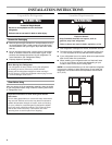
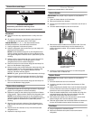
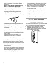
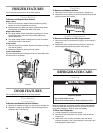
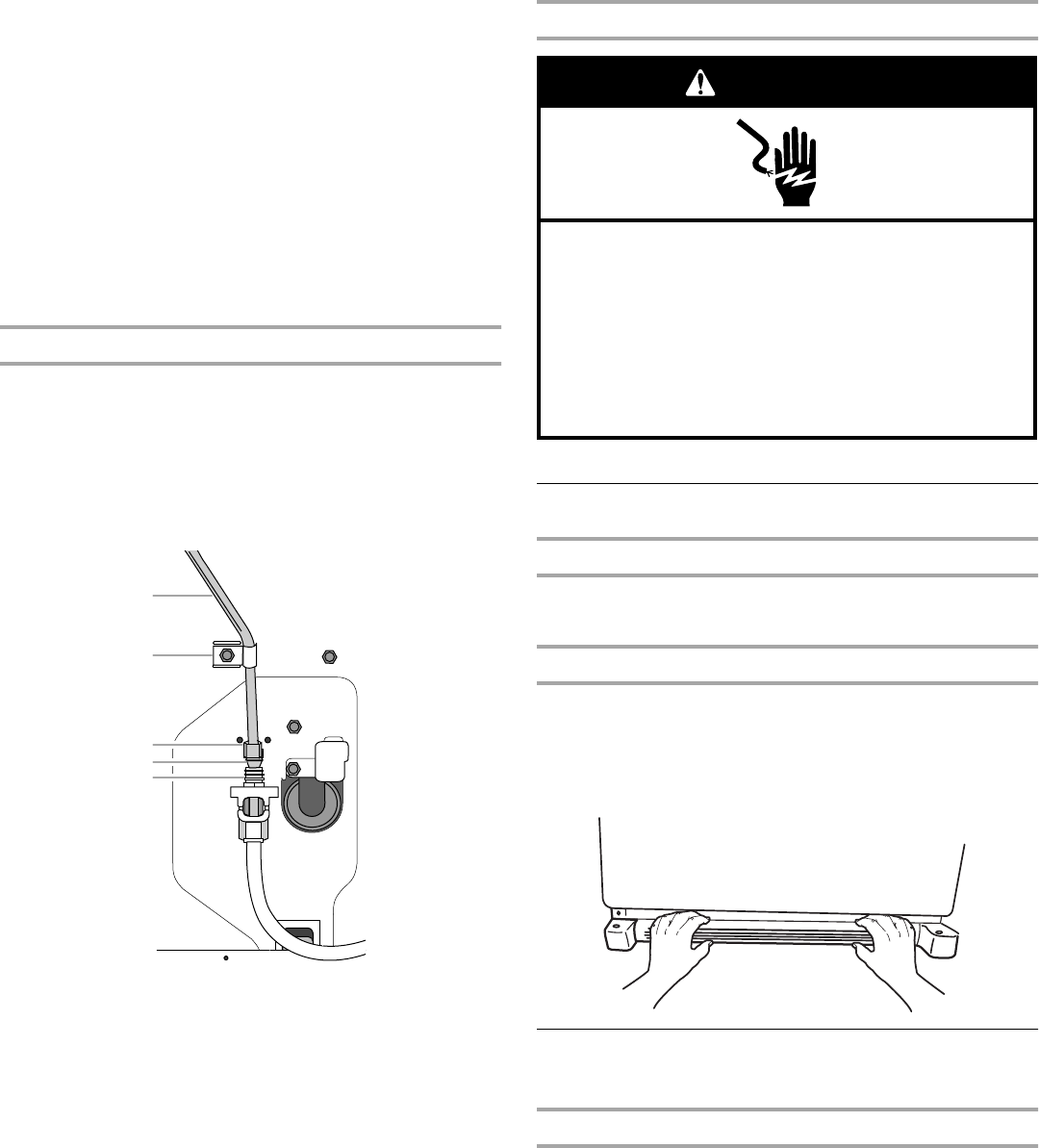
1. Remove plastic cap from water valve inlet port. Attach the
copper tube to the valve inlet using a compression nut and
sleeve as shown. Tighten the compression nut. Do not
overtighten. Confirm copper tubing is secure by pulling on
copper tubing.
2. Create a service loop using extreme care to avoid kinks.
Secure copper tubing to refrigerator cabinet with a “P”
clamp.
3. Turn on water supply to refrigerator and check for leaks.
Correct any leaks.
Complete the Installation
Plug in refrigerator or reconnect power.
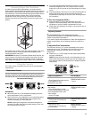
Base Grille
Remove the Base Grille
1. Grasp the grille with both hands.
2. Pull the grille toward you.
Replace the Base Grille
1. See the markings on the inside of the base grille for proper
placement.
2. Align the grille mounting clips with the cabinet slots.
3. Push the grille firmly into the cabinet slots until it snaps into
place.
Refrigerator Doors
Graphics are included later in this section.
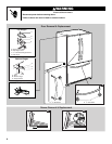
Remove and Replace Handles
1. Using a ³⁄₃₂" Allen wrench, loosen the two set screws located
on the side of each handle. See Graphics 1 and 2.
2. Pull the handle straight out from the door. Make sure you
keep the screws for reattaching the handles.
3. To replace the handles, reverse the directions.
A.Copper tubing
B.“P” clamp
C.Compression nut
D.Compression sleeve
E.Water valve inlet port
A
B
C
D
E
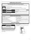
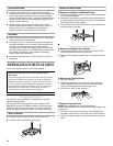
Electrical Shock Hazard
Plug into a grounded 3 prong outlet.
Do not remove ground prong.
Do not use an adapter.
Do not use an extension cord.
Failure to follow these instructions can result in death,
fire, or electrical shock.
WARNING