


18
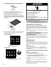
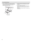
Gas pressure regulator
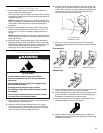
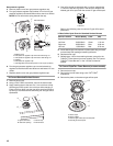
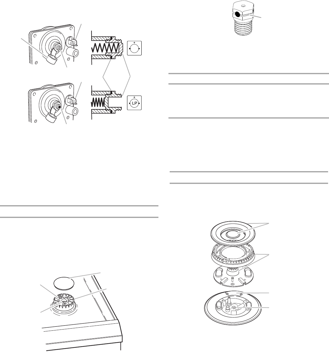
4. Remove plastic cover from gas pressure regulator cap.
5.
Turn gas pressure regulator cap (marked “N” on front of gas
pressure regulator) counterclockwise with a wrench to remove.
NOTE: Do not remove the spring beneath the cap.
6. Turn the gas pressure regulator cap over and reinstall on
regulator so that the hollow end faces out and letters “LP” are
visible.
7. Replace plastic cover over gas pressure regulator cap.
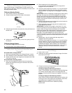
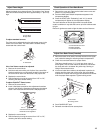
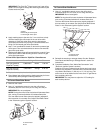
To Convert Standard Surface Burners
1. Remove burner cap.
2. Using a T20
®
TORX
®
screwdriver, remove the burner base.
3. Apply masking tape to the end of a 7 mm nut driver to help
hold the gas orifice spud in the nut driver while changing it.
Press nut driver down onto the gas orifice spud and remove
by turning it counterclockwise and lifting out. Set gas orifice
spud aside.
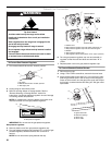
4. Gas orifice spuds are stamped with a number, marked with
1 color dot, and have a groove in the hex area. Replace the
Natural gas orifice spud with the correct LP gas orifice spud.
Refer to the following chart for correct LP gas orifice spud
placement.
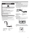
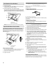
LP Gas Orifice Spud Chart for Standard Surface Burners
5. Place Natural gas orifice spuds in plastic parts bag for future
use and keep with package containing literature.
6. Replace burner cap.
7. Repeat steps 1-6 for the remaining burners, except for the
TripleTier
®
Flame burner (on some models). See “To Convert
TripleTier
®
Flame Burners” in the “LP Gas Conversion”
section.
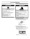
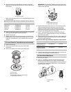
To Convert TripleTier
®
Flame Burners (on some models)
1. Remove burner cap.
2. Remove the burner head using a size T20
®
TORX
®
screwdriver.
3. Remove the plate on the external gas orifice spud.
A.Plastic cover
B.Gas pressure regulator cap with solid end facing out
C.Gas pressure regulator cap with hollow end facing out
D.Washer
E.Gas pressure regulator cap
F. Gas regulator shutoff valve (shown in the “open” position)
A.Igniter electrode
B.Gas tube opening
C.Burner cap
D.Burner base
A
B
C
D
N
Side view before
Side view after
E
F
F
A
B
C
D
A.Groove
Burner Location Burner Rating Color Size
Right front
Left front
Right rear
Left rear
5,000 Btu/h
13,000 Btu/h
10,000 Btu/h
5,000 Btu/h
Red
Green
Blue
Red
0.70 mm
1.10 mm
0.95 mm
0.70 mm
A.Burner caps
B.Burner heads
C.External gas orifice spud access plate
D.Internal gas orifice spud
A
A
B
C
D