


5
- For Insert installation -
Preparation Before Installation
NOTE: TO AVOID DAMAGE TO YOUR HOOD, PREVENT
DEBRIS FROM ENTERING THE VENT OPENING.
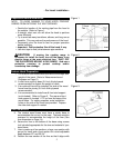
•
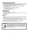
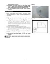
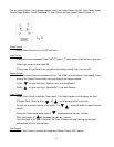
Decide the location of the venting pipe from the hood to
the outside. Refer to Figure 1.
•
A straight, short vent run will allow the hood to perform
more efficiently.
•
Try to avoid as many transitions, elbows, and long run as
possible. This may reduce the performance of the hood.
•
Temporarily wire the hood to test for proper operation
before installing.
•
Important: Peel protective film off the hood, if any.
•
Use duct tape to seal joints between pipe sections.
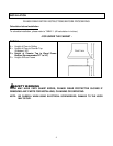
CAUTION
: If moving the cooking range is
necessary to install the hood, turn off the power in an
electric range at the main electrical box. SHUT OFF
THE GAS BEFORE MOVING A GAS RANGE. And use a
protective covering to protect cooktop and/or
countertop from damage.
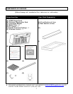
Custom Hood Preparation
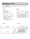
1. The custom hood frame must be sized to the shape and
weight of the insert. Refer to Measurements and
Diagrams on Page 13.
2. It must have a sturdy base (3/4 inch thick plywood
recommended) to sustain the weight of insert.
3. If an optional liner will be installed, the side of the wood
frame must be sturdy (3/4 inch thick plywood
recommended).
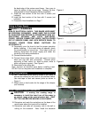
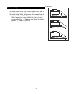
4. It is recommended to install rear & front stud support
(not included). Refer to Figure 2. The rear and front
stud support is located 1-1/2” up from the base of the
wood frame. For safety purposes, extra installation
holes on the side of the insert are provided. Prepare
the side stud support if needed.
Liner Installation
5. The custom wood frame must have a sturdy base to
accommodate the cut-out for the inset. The base must be
recessed to accommodate the height of the liner (See
liner dimension on Page 14)
6. Secure the liner to the bottom of the base using screws
(not included) appropriate for the size and material of your
wood frame.
7. Liner is made up of two sections: a large, rear section with
pre-cut for insert and a front section for a total adjustable
depth between 23” and 25-3/4”.
8. Position the rear section of the liner so that it aligns with
Figure 1
Figure 2
Figure 3