


7
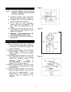
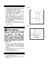
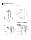
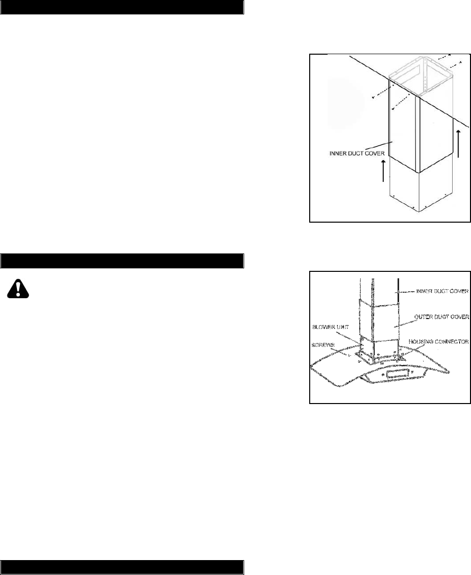
11. Slide the inner duct cover up and secure to
the telescopic stack with four (ST 3 x 15)
screws (provided). Refer to Figure 7.
12. With assistance, slide the outer duct cover
to the blower unit and ask assistant to hold
steady until step 15 is completed.
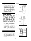
13. Attach glass canopy with LCD screen
underneath the blower unit. Make sure
blower unit is inside the housing connector.
Refer to the PARTS LIST on pages 16-17.
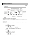
14. Secure the housing connector to the blower
unit with eight (M5 x 15) screws (provided)
as shown in Figure 8.
15. Ask assistant to slide outer duct cover
downward so it rest within the grooves of
the glass canopy.
Connection to LCD Screen
SAFETY WARNING
RISK OF ELECTRICAL SHOCK. THIS
RANGE HOOD MUST BE PROPERLY
GROUNDED. MAKE SURE THIS IS DONE
BY QUALIFIED ELECTRICIAN IN
ACCORDANCE WITH ALL APPLICABLE
NATIONAL AND LOCAL ELECTRICAL
CODES. BEFORE CONNECTING WIRES,
SWITCH POWER OFF AT SERVICE PANEL
AND LOCK SERVICE PANEL TO PREVENT
POWER FROM BEING SWITCHED ON
ACCIDENTALLY.
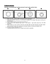
16. Remove front baffle filter (directly behind
LCD screen). When facing the LCD screen,
turn knobs slightly to left to release baffle
filter. CAUTION: DO NOT OVERTURN
KNOBS.
17. Connect the wires according to connector
color to the blower unit.
18. Place baffle filters back in place.
Final Assembly
19. Turn power ON in control panel. Check all
lights and fan operation.
20. Make sure to leave this manual for the
homeowner.
Figure 7
Figure 8
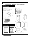
Duct Cover Installation