


Draft is caused by the gases inside the flue being hotter and lighter than the air outside, thus the
rising heated gases carry out the products of combustion. Since the flue “sucks” gases up the flue, it
is this suction that draws air into the pedestal area to feed the burn pot with the air needed for an
efficient, blue-flame burn. This will depend on the flue’s ability to provide a consistent negative
pressure. There is no substitute for a warm, efficient chimney/pipe system. If the flue gases cool
too quickly, draft will slow and combustion will not be as efficient. Do not skimp on the flue
system. A good rule of thumb on chimney height is a minimum of 12’ from the stove top to
termination. Location of chimney and other factors may require more or less chimney height.
An insulated chimney is a must in order to maintain the heat inside the chimney for proper
flow of gases. Use a Class “L”, 4” diameter, insulated chimney that has been tested to U.L. 641
when passing through combustibles, or use 4” or 5” diameter Class “A” insulated HT type chimney.
Due consideration must be given to your particular climate zone. Extreme cold ‘attacks’ the
chimney’s ability to maintain an efficient draft. The stove pipe connector may be single-wall black
pipe with tight fitting joints (mobile home connectors must be double-wall). Make sure that all
joints are securely fastened with three sheet metal screws, including the connection at the stove as
well as at the ceiling or chimney connection. The Shasta may also be connected to a masonry
chimney, but it is recommended that it be lined with a 4” stainless steel liner and insulated as well.
Use and install all piping according to the manufacturers listed clearances.
Certain atmospheric conditions such as high winds will cause a change (increase or
decrease) in the negative pressure inside the flue and thus inside the stove. To compensate for this,
your stove has a draft or flue stabilizer which is a barometric damper located at the rear back of
your stove. Under certain geographic or atmospheric conditions, it may be necessary to install a
wind-beater vacuum cap or a wind-directional cap. See your dealer for information. Upon
installation of the stove and after lighting and warm-up, the rear cover must be removed and the
draft stabilizer adjusted. Its purpose is to allow more or less air to travel into the flue to compensate
for a change in the flue draft. Adjustment of the draft stabilizer will be discussed in Section 4.
SECTION 3
Fuel tank installation and fuel line connections
OIL:
Your Kuma model Shasta comes with a carburetor set for an average of a 2.35 cc.
viscosity rating. You should be able to burn either #1 or #2 fuel with adjustments to the
carburetor. Bio-diesel may also be successfully burned in the Oil Classic. Due consideration to
fuel grades should be noted. #1 Fuel oil, K-1, or kerosene will burn much cleaner than #2 fuel
and requires less maintenance. #2 fuel or diesel grades of fuel are fine to burn, however there
are combustibles present in # 2 fuel that become solids when they are burned, thereby requiring
more frequent cleaning of the decoker and burner.
TANK:
The fuel tank should be clean (second-hand tanks not recommended), so a new tank is
advised. Steel tanks require more maintenance such as painting to prevent rust. A polyethylene
tank is preferred as it will never rot or rust, and is basically maintenance-free. A tank with a
larger capacity will require less fillings as well as an opportunity to obtain better pricing for fuel
oil in greater quantities. Avoid placing the tank in direct sunlight. Warm tanks will condense
moisture which will fall to the bottom of your tank where it will need to be drained to prevent
valve damage and/or freezing and stopping oil flow. Also, due consideration should be given to
accessibility to the tank for delivery trucks.
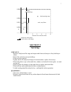
The ideal tank should have two bottom-end outlets: one for fuel supply to the stove, and
one to drain off any water and dirt. To be able to do this, the tank must be installed with a
“fall” of at least 1/4” per foot of tank length. The fuel supply will come from the high end of
the tank and the lower end will be used for draining condensation and impurities. If the tank
has only one outlet, be sure to tip the tank away from the outlet slightly, as described above.
Brick or cement foundation for the tank is advised.
3