NOTE: DIAGRAMS & ILLUSTRATIONS NOT TO SCALE.
Printed in U.S.A. © 2002 by LENNOX
P/N 750,150M REV. N/C 8/2002
The manufacturer reserves the right to make changes at any time, without notice, in
design, materials, specifications, prices and also to discontinue colors, styles and
products. Consult your local distributor for fireplace code information.
1110 West Taft Avenue • Orange, CA 92865
NOTE: DIAGRAMS & ILLUSTRATIONS NOT TO SCALE.
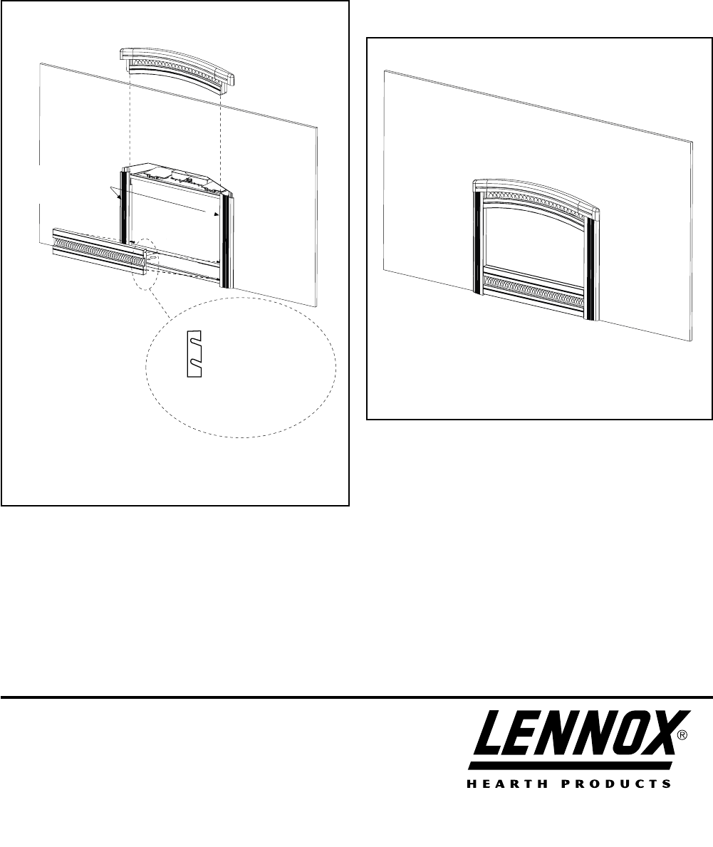
Figure 3
Installed Fireplace Cast Iron Facade and Grills
Figure 4
Top Cast Iron (Arch) Piece
Bottom Cast Iron Piece
Installing the Top and Bottom Cast Iron Pieces
Previouly Installed
Cast Iron Side Pieces
Bottom Cast Iron Piece Detail
Showing Installation
Orientation
TOP
Slot orientation
indicates facade top.
Step 4. Slide the top cast iron piece (arched piece) down between and
behind the side pieces as shown in
Figure 3
. See
Figure 4
for
the final appearance of the installed cast iron facade .
Step 5. Hook the bottom cast iron piece (with the top, up, as shown
in
Figure 3)
to the 4 holding screws protruding from the two
cast iron side pieces as shown in
Figure 3
. See
Figure 4
for
the final appearance of the installed cast iron facade.


