


9
ENGLISH
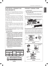
ELECTRICAL CONNECTIONS
4-WIRE CONNECTION WITH
A POWER SUPPLY CORD
• Only a 4-conductor power-supply cord kit rated
120/240 volts, 50 amperes and marked for use
with ranges with closedloop connectors or
open-end spade lugs with upturned ends shall
be used. The middle (neutral) wire of the power
cord or 4-wire conduit has to be connected to
the middle post of the main terminal block. The
other two wires of the power cord or conduit
have to be connected to the outside posts of
the main terminal connection block. The 4th
ground wire must be connected to the frame of
the range with the ground screw.
- Failure to do so can result in electrical shock,
severe personal injury or death.
WARNING
Follow the instructions under “CONNECT RANGE CORD”
on page 7 to correctly install the strain relief.
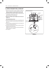
1. Remove the lower 3 screws from the terminal block
and retain them. (Refer to Figure 9.)
Remove the ground screw and retain it.
2. Remove ground strap and discard as shown in
Figure 9.
Do not discard any screws.
3. Insert the ground screw into the power cord ground
wire terminal ring and secure it to the range frame.
4. Insert the 3 screws through each power cord terminal
ring and into the lower terminals of the terminal block.
Make sure that the center wire (white/neutral) is
connected to the center lower position of the terminal
block.
Tighten 3 screws securely into the terminal block.
5. Go to page 11.
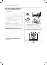
4-wire connection
Terminal
block
Conduit
connection plate
Ground screw
Remove ground
strap and discard
Ground
strap
Black White Red
FIGURE 9
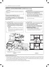
3-WIRE CONNECTION: CONDUIT
Install the conduit as follows:
Remove the Conduit connection plate from the rear of
lower oven and rotate it as shown in Figure 5. The
conduit hole (1
1
/8”) must be used.
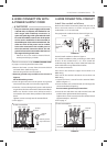
First, prepare the conduit wires as shown in Figure 10.
3 wire 4 wire
Conduit
connection
plate
or
Ground
wire
FIGURE 10
Second, install conduit as shown in Figure 6.
For conduit installations, after purchasing a strain relief,
insert it in the conduit hole (1
1
/8”). Then install the
conduit through the body of strain relief and fasten the
strain relief with its ring. Reinstall the bracket.
For conduit connections :
If the wire in the conduit is copper it must be 8 or 10
AWG wiring.
If the wire in the conduit is aluminum it must be 6 or 8
AWG wiring.
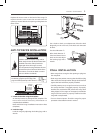
1. Loosen the lower 3 screws from the terminal block.
(Refer to Figure 11.)
2. Insert the bare wire (white/neutral) end through the
center terminal block opening.
Do not remove ground strap connections.
3. Insert the two side bare wire ends into the lower left
and the lower right terminal block opening.
Tighten the 3 screws securely into the terminal block.
(approximately 35 - 50 IN-LB)
4. Go to page 11.
3-wire connection
Terminal
block
Wire ends
Conduit
connection plate
Black White Red
FIGURE 11