


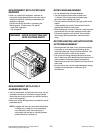
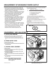

I. HIGH VOLTAGE TRANSFORMER
REMOVAL
1) Discharge the high voltage capacitor.
2) Disconnect the lead wire from magnetron, high voltage
transformer, and capacitor.
3) Remove the screw holding the high voltage
transformer to the baseplate.
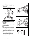
J. FAN MOTOR ASSEMBLY REMOVAL
1) Discharge the high voltage capacitor.
2) Disconnect the lead wire from fan motor and high
voltage capacitor.
3) Remove the two screws holding the the suction guide
ASS’Y to the oven cavity and remove the high voltage
diode earth screw.
4) Remove the two screws holding the fan motor ASS’Y
to the suction guide ASS’Y.
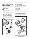
K. HIGH VOLTAGE CAPACITOR AND
DIODE REMOVAL
1) Discharge the high voltage capacitor.
2) Disconnect the lead wire from fan motor and high
voltage capacitor.
3) Remove the screw holding the suction guide ASS’Y to
the oven cavity and remove the high voltage diode
earth screw.
4) Remove the screw holding the high voltage capacitor
bracket.
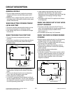
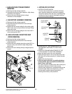
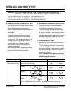
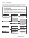
L. INTERLOCK SYSTEM
1) INTERLOCK MECHANISM
The door lock mechanism is a device which has
been specially designed to eliminate completely
microwave activity when the door is opened during
cooking and thus to prevent the danger resulting
from the microwave leakage.
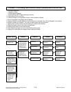
2) MOUNTING OF THE PRIMARY/MONITOR/
SECONDARY SWITCHES TO THE LATCH
BOARD
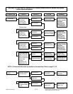
3) INSTALLATION AND ADJUSTMENT OF THE
LATCH BOARD TO THE OVEN ASSEMBLY
• Mount the latch board to the oven assembly.
• Adjust the latch board in the arrow direction so that
oven door will not have any play in it when the door
is closed.
• Tighten the mounting screw.
• Check for play in the door by pushing the door
release button. Door movement should be less
than 0.5 mm. (1/64 inch)
Don't push the door release button while making this
adjustment. Make sure that the latch moves
smoothly after adjustment is completed and that the
screws are tight. Make sure the primary, monitor,
and secondary switches operate properly by
following the continuity test procedure.
5-6
H.V.
Transformer
Fan Motor
ASS’Y
Suction
Guide
H.V.
Capacitor
H.V.
Diode
ADJUSTMENT
DIRECTION
SECONDARY
SWITCH
MONITOR
SWITCH
PRIMARY
SWITCH
LGE Internal Use OnlyCopyright © 2007 LG Electronics. Inc. All right reserved.
Only for training and service purposes