


REFER TO SL-16655, LIEBERT XTREME DENSITY SYSTEM DESIGN MANUAL, AND SL-16674, LIEBERT XDC USER MANUAL FOR ADDITIONAL DETAIL.
DPN001599
REV 12/11
REV 4
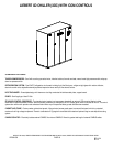
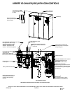
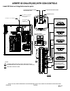
LIEBERT XD CHILLER (XDC) WITH iCOM CONTROLS
PAGE 5/6
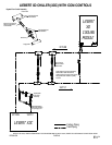
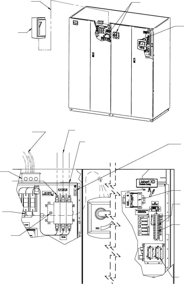
Three phase electric
service not provided
by Liebert.
Field supplied disconnect
switch may not be required,
check local codes.
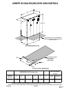
NOTE: Refer to specification sheet for full load amp. and wire size amp. ratings.
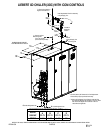
60HZ COMPONENTS SHOWN
Factory installed disconnect switch
EARTH GROUND CONNECTION
Connection terminal for field supplied
earth grounding wire.
HEAT REJECTION CONNECTION (R-407C Side)
Field supplied 24V. Class 1 wiring to
interlock heat rejection from pigtails:
70A & 71A - Compressor 1 circuit
70B & 71B - Compressor 2 circuit
70C & 71C - Dual Cool relay (optional)
THREE PHASE CONNECTION
Electric service connection terminals
Electrical handy box factory
installed with cover.
Factory wired to components
on electric panel
EARTH GROUND BAR (50Hz only)
Connection terminal with factory
ground from each high voltage
component
Three phase electric service
not by Liebert.
ELECTRIC CONDUIT KNOCKOUTS
On top of electric box. Knockout size
2 in (51 mm)
ALARM AND WARNING OUTPUT RELAYS
Field supplied 24V Class 2 wire for
special alarms.
(Not to exceed 1.0A @ 24v each.)
REMOTE UNIT SHUTDOWN
Replace existing jumper between terminals
37 & 38 with normally closed switch having
a minimum 50VA rating. Use field supplied
24V Class 2 wire.
INTELLISLOTS
Two Liebert Intellislots for optional
OCWEB-LBDS or OC485-LBDS card.
®
®
iCOM display
Factory installed unit
disconnect switches
CANBUS ISOLATOR