


Start the Liebert XDP with Liebert iCOM
65
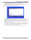
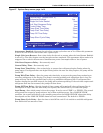
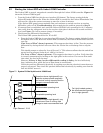
5.2 Starting the Liebert XDP with Liebert iCOM Controller
The Liebert XDP is started, stopped and controlled through the Liebert iCOM controller. Figure 24
shows the Liebert iCOM keypad.
1. Turn the Liebert XDP On with the user interface (I/O button). The factory-setting defaults
Liebert XD module fans to On. When the Liebert XDP is turned On, the Liebert XD modules’ fans
will turn On. Allow the system to attempt to start for at least 2 minutes.
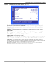
If the Liebert XDP pump cannot maintain flow and continues to switch over due to starting
difficulties, refer to
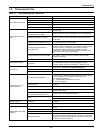
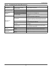
7.0 - Troubleshooting. After remedying the problem, proceed to Step 2.
2. If constant flow is established, wait until the Liebert XDP has been operating for 10-15 minutes,
then verify that the refrigerant level in the receiver sight glass is between the second and third
level (see
Figure 71). Add or remove charge, if necessary.
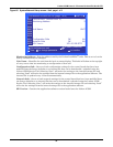
3. Check pressure differential functionality:
The Liebert XDP system should be On. If it is Off:
a. Turn the Liebert XDP On via user interface (I/O button). The factory-setting defaults Liebert
XD module fans to On. When the Liebert XDP is turned On, the Liebert XD modules’ fans will
turn On.
If no “Loss of Flow” alarm is present—This suggests that there is flow. Test the pressure
differential by closing the ball valve on either the suction line or discharge line to stop the
flow.
This should prompt an alarm for “loss of flow on P1.” This alarm confirms that the switch has
opened on low pressure (below 6 psi; 41kPa; 0.41 bars).
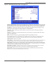
If a “Loss of Flow” alarm is present—This suggests that there is no flow. Verify that this
is correctly annunciated by looking at the sight glass in the receiver. If a true no-flow condi
-
tion exists, the level will not move.
However, if there is flow, but the differential reading is faulty, the level will slowly
drop, indicating flow, while the loss of flow alarm is annunciated.
Check the pressure differential physically by making sure that the electrical connections are
properly connected. Then check the pressure differential electrically by making sure that the
unit has 24VAC across it.
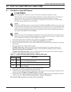
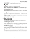
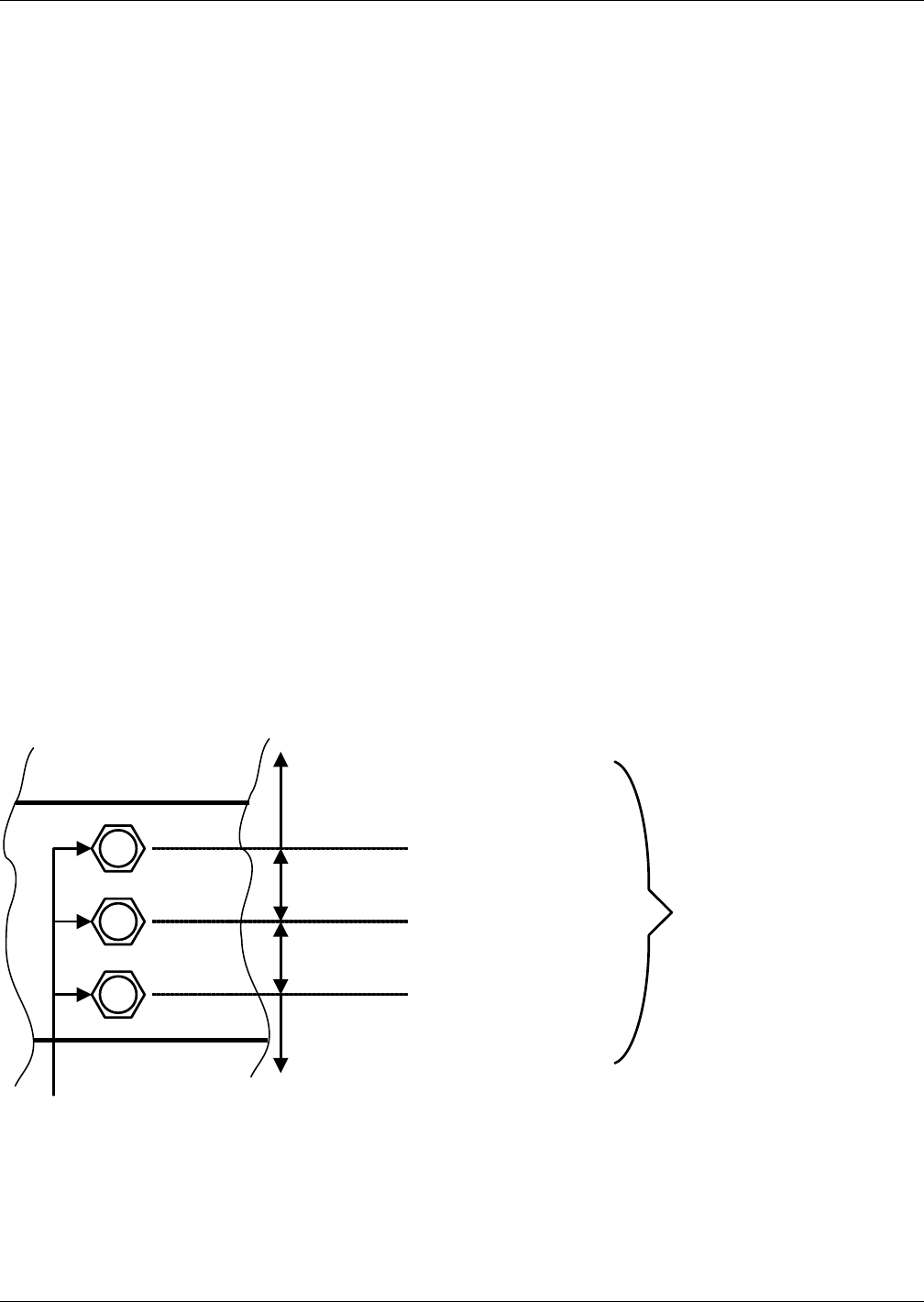
Figure 71 System R-134a liquid level at 160kW load
Operation above sight glass #3 can
make the system operate erratically
and reduce cooling capacity. Reduce
charge to recommended level.
Recommended operating level
Acceptable operating level
Operation below sight glass #1 may
cause loss of flow or cooling. Add
charge to reach recommended level.
For lightly loaded systems,
the recommended operating
level is sight glass #2.
Sight Glasses 1, 2 & 3