


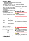
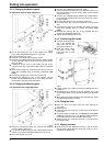
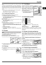

4.3.3 Changing the bearing parts
for appliances without height adjustment
Fig. 5
u
Lift out the bearing pin
Fig. 5 (22)
together with washer
Fig. 5 (23)
and adjustable-height foot*
Fig. 5 (24)
.
u
Lift off the stopper
Fig. 5 (21)
.
u
Unscrew
Fig. 5 (26)
the turn hinge
Fig. 5 (25)
.
u
Unscrew
Fig. 5 (29)
the bearing element
Fig. 5 (28)
, transfer
it to the opposite location hole of the turn hinge and screw it
firmly into place.
u
Carefully lift off the cover on the handle side
Fig. 5 (27)
,
undo the screw
Fig. 6 (40)
and transfer both to the opposite
side.
u
Screw the turn hinge
Fig. 5 (25)
firmly into place on the new
hinge side, possibly using a cordless screwdriver (with
4 Nm).
u
Re-insert the stopper
Fig. 5 (21)
into the other hole.
u
Re-insert the bearing pin
Fig. 5 (22)
together with the
washer and adjustable-height foot*. In so doing, pay atten-
tion that the locating lug points backwards
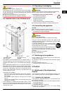
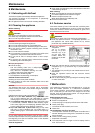
4.3.4 Changing the bearing parts
For appliances with height adjustment
Fig. 6
u
Using the accompanying Allen key, unscrew the threaded
pin
Fig. 6 (40)
by about 1 turn.
u
Turn and lift out the bearing pin
Fig. 6 (22)
together with the
washer
Fig. 6 (23)
and adjustable-height foot*
Fig. 6 (24)
.
u
Lift out the stopper
Fig. 6 (21)
.
u
Unscrew
Fig. 6 (26)
the turn hinge
Fig. 6 (25)
.
u
Fully unscrew the threaded pin
Fig. 6 (40)
and screw it in on
the opposite side, at the turn hinge, until it is flush outside
with the turn hinge.
u
Unscrew
Fig. 6 (29)
the bearing element
Fig. 6 (28)
transfer it
to the opposite location hole of the turn hinge and screw it
firmly into place.
u
Re-insert the stopper
Fig. 6 (21)
into the other hole.
u
Undo the screw
Fig. 6 (27)
and transfer it to the opposite
side.
u
Screw the turn hinge
Fig. 6 (25)
firmly into place on the new
hinge side, possibly using a cordless screwdriver (with
4 Nm).
u
Re-insert the bearing pin
Fig. 6 (22)
together with the
washer and adjustable-height foot*.
u
Tighten the threaded pin
Fig. 6 (40)
.
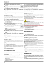
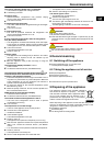
4.3.5 Transferring the handle
u
Transfer the spring clamp
Fig. 7 (31)
: Depress the
latch nose and pull the
spring clamp off over it.
u
Slide the spring clamp
into place on the new
hinge side until it clicks
into place.
Fig. 7
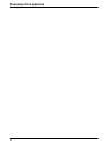
Fig. 8
u
Lift the stopper
Fig. 8 (33)
out of the door bearing bush and
transfer it.
u
Dismantle the door handle
Fig. 8 (32)
, stoppers
Fig. 8 (33)
and pressure plates*
Fig. 8 (34)
and transfer to the opposite
side.
u
When fitting the pressure plates on the opposite side, make
sure they snap properly into place.*
4.3.6 Fitting the door
u
Place the door from above onto the lower bearing pin
Fig. 6 (22)
.
u
Close the door.
u
Insert the upper turn hinge
Fig. 4 (12)
in the door on the new
hinge side.
u
Screw the upper turn hinge
Fig. 4 (12)
firmly into place (with
4 Nm)(2x Torx® 25)
Fig. 4 (13)
. Possibly make preliminary
holes with a bradawl or use a cordless screwdriver.
u
Snap the cover
Fig. 4 (10)
and cover
Fig. 4 (11)
into place at
the opposite side.
4.3.7 Aligning the door
u
Align the door to the appliance housing by way of the two
oblong holes in the bottom turn hinge
Fig. 6 (25)
. To do so,
unscrew the middle screw.
Putting into operation
6