


Impinger II –Advantage Service Manual - Domestic
17
REMOVAL, INSTALLATION, AND ADJUSTMENT
IMPINGER II ADVANTAGE
CAUTION!
BEFORE REMOVING OR INSTALLING ANY COMPONENT IN THE IMPINGER OVEN, BE SURE TO DISCONNECT
ELECTRICAL POWER AND GAS SUPPLY.
MOTOR, MAIN FAN
1. Shut off power at main breaker.
2. Remove motor cover from back of oven.
3. Remove wires for motor and mark for reassembly.
4. Remove hex head bolts from the oven back and slide back straight out of the oven.
5. Loosen bolt from fan hub and remove fan from motor shaft.
NOTE: Measure distance from fan blade to rear wall assembly before removal to aid in reassembly.
6. Remove the bolts from the motor mount and remove motor clamp. Slide the motor assembly out of the
oven back.
7. Remove motor by removing the four (4) mounting nuts and washers.
8. Reassemble in reverse order. When motor mount assembly is set on the oven back, align motor shaft in
the center of the hole. Set fan assembly on the motor shaft.
NOTE: It is recommended that an anti-seize compound be brushed on to the bolts around the back and
motor mount bracket before assembly.
FAN, MAIN
1. Shut off power at main breaker.
2. Remove back assembly. (See motor, main fan)
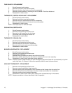
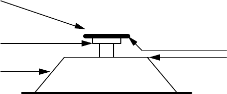
3. Reinstall and locate fan so that the bottom of the fan spider is 1 1/2" from the top of the oven back cone.
(See drawing)
FAN HUB
CONE
FAN SPIDER
1 1/2 INCH
NOTE: MEASUREMENT MUST BE
MADE FROM CONE TO FAN SPIDER
CAPACITOR, MOTOR
1. Shut off power at main breaker.
2. Remove control box cover and front panel.
3. Discharge capacitor.
4. Remove and replace.
ON/OFF SWITCH - REPLACEMENT
1. Shut off power at main breaker.
2. Remove control box cover.
3. Remove front panel.
4. Depress spring clips on side of switch and push out.
5. Remove wires from back of switch, note wire number and location.
6. Reassemble in reverse order and check system operation.
NOTE: Make sure switch housing is fully seated in control box housing.