Impinger I – Adv Digital – Gas Service Manual – International
9
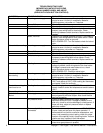
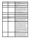
there is voltage to the pilot valve, but there is no gas
pressure, replace gas valve.
Pilot tube Check for gas pressure at pilot tube. Disconnect pilot
tube at burner and connect manometer. If there is no
gas pressure, check for blockage in pilot tube. Repair or
replace as needed.
Pilot orifice If there is gas pressure at the pilot tube, check the pilot
orifice for damage or obstructions. Replace pilot orifice
as needed.
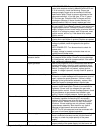
Flame will not stay on Flame sensor To check flame sensor operation, connect a digital
multimeter (capable of measuring D.C. microamps)
between the flame sensor wire and the flame sensor
connection on the ignition control (terminal #13). Flame
sensor current is to be 0.7 microamps, minimum. If
these readings are not achieved, replace igniter/sensor
assembly. Also check for any type of damage to flame
sensor wire and connections.
NOTE: The D.C. microamp test must be conducted with
the oven in low flame (bypass) operation.
Power supply Set the temperature to the lowest temperature setting. If
there is sufficient microamp current, but the flame will
not stay lit, check for proper polarity of the power supply.
Ignition control If there is sufficient microamp current, and there is
proper polarity of the power supply, but the burner will
not stay lit, check the reset button for the ignition control.
If the above test is okay, replace the ignition control.
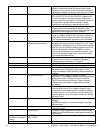
NOTE: Flame should be on at
this time
Low flame is on, but
no main flame
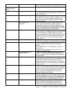
Control transformer Check for supply voltage to primary of control
transformer. If no voltage is present, trace wiring back to
oven power switch. If voltage is present, check for
24VAC at transformer secondary. If there is primary
voltage, but no secondary voltage, replace control
transformer.
Oven control Check for 24VAC supply to oven control. If no voltage is
present, trace wiring back to control transformer. Check
for supply voltage to oven control. If no voltage is
present, trace wiring back to ignition control. If voltage is
present, check for a read-out on the display. If there is
no read-out on the display, replace oven control. If there
is a read-out on the display, set the oven control to
maximum temperature (see installation operations
manual for temperature adjustment). With the oven
control at maximum temperature, check for supply
voltage to the temperature regulation valve. If there is
voltage at the temperature regulation valve, proceed to
“Temperature regulation valve “. If there is no voltage at
the temperature regulation valve, trace wiring back to
the oven control. If there is no voltage output at the oven
control, check the read-out on the oven control. If the
oven control reads “PROBE FAIL” this indicates that the
thermocouple has failed or become disconnected from
the oven control
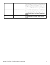
Thermocouple Check to see that the thermocouple is securely
connected to the oven control. If the thermocouple is
connected to the oven control, and the display indicates
“PROBE FAIL”, disconnect the thermocouple from the
oven control and measure the resistance of the
thermocouple. The thermocouple should read approx.
11Ω. If these readings are not achieved, replace the
thermocouple. If these readings are correct, proceed.


