


Impinger I -–Adv Digital – Electric Service Manual - International
3
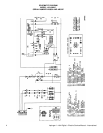
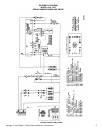
SEQUENCE OF OPERATION
IMPINGER ADVANTAGE
SERIAL NUMBER N28654 AND ABOVE
(OVENS WITH PUSH BUTTON CONTROLS)
MODEL 1454 220/380VAC 50 HZ. 3 PHASE
MODEL 1455 240/415VAC 50 HZ. 3 PHASE
POWER SUPPLY Electrical power is to be supplied to the oven by a five conductor
service.
Brown conductor is hot.
Black conductor is hot.
Black conductor is hot.
Blue conductor is neutral.
Green conductor is ground.
CONTROL BOX AUTO
COOL DOWN
When the temperature in the control box reaches 120°F ± 3°F (48.9°C
± 1.7°C), the cooling fan thermostat will switch power to the control
box cooling fan. The thermostat will interrupt power to the cooling fan
when the control box temperature falls to 100°F ± 3°F (37°C ± 1.7°C).
MAIN FAN CIRCUIT Electrical power is permanently supplied through three 50 A fuses to
the normally open contacts of the heat relay. Power is also supplied,
through the 10 Amp motor and control fuse, through the normally
closed control box hi-limit thermostat, to the normally open oven power
switch. Power is also supplied to the control box cooling fan
thermostat. Closing the oven power switch supplies line voltage to the
main fan motor. Closing the oven power switch also supplies line
voltage to the heat circuit and to the primary of the oven control
transformer.
HEAT CIRCUIT Closing the oven power switch supplies line voltage through the main
fan air pressure switch, through the normally closed oven cavity hi-limit
thermostat, to the oven control
TEMPERATURE CONTROL Closing the oven power switch supplies line voltage to the primary of
the control transformer and through the air pressure switch and oven
cavity hi-limit, to the oven control. Secondary voltage, 24VAC, is
supplied to the oven control. The oven control is set to desired
temperature. The thermocouple will provide varying millivolts to the
oven control. The oven control supplies line voltage to the heat
contactor at intermittent intervals to maintain desired temperature. The
display on the oven control will indicate when the heat contactor is
energized.
NOTE: The display also indicates oven temperature.
CONVEYOR DRIVE Closing the oven power switch supplies line voltage to the conveyor
motor and to the primary of the control transformer. Secondary
voltage, 24VAC, is supplied to the oven control. Setting the oven
control to the desired time outputs voltage, through a reversing switch,
to the conveyor motor.
NOTE: The conveyor system uses a hall effect sensor and magnet to
prove operation of the conveyor motor. If the motor is not running,
“BELT JAM” is indicated on the display.