Low Profile –1600 Series Advantage Digital Service Manual – Int’l
14
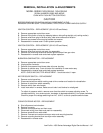
BURNER ALARM - REPLACEMENT
A. Remove appropriate control box cover.
B. Remove 2 wires from alarm, note wire numbers and location.
C. Remove retainer cover from alarm and remove assembly from control box.
D. Reassemble in reverse order and check system operation.
SPARK GENERATOR – REPLACEMENT
A. Remove appropriate control box cover.
B. Remove 2 wires for spark generator.
C. Unplug connector on bottom of spark generator.
D. Remove 2 mounting screws and remove generator assembly.
E. Reassemble in reverse order and check system operation.
IGNITER SENSOR – REPLACEMENT
A. Remove appropriate control box cover.
B. Remove gas valve assembly ( see gas valve )
C. Remove screws from burner tube and pull burner assembly out.
D. Remove wire connectors from igniter sensor assembly.
E. Remove screws from mounting bracket and remove assembly.
F. Reassemble in reverse order and check system operation.
NOTE: After installation, check all pipe fittings for leaks.
SWITCH, BURNER RESET – REPLACEMENT
A. Remove appropriate control box cover.
B. Disconnect wires from ignition control (see ignition control). Note wire number and location for
reassembly.
C. Pull off black operating knob and remove hex mounting nut.
D. Reassemble in reverse order.
TEMPERATURE REGULATING VALVE – REPLACEMENT
A. Remove appropriate control box cover.
B. Remove bypass tube assembly.
C. Remove 4 nuts from burner orifice bracket.
D. Disconnect pipe union.
E. Disconnect 2 wires from valve and remove assembly.
F. Remove gas piping from old valve and install on new valve.
G. Reassemble in reverse order and check system operation. NOTE: Check all gas line fittings for
leaks and insure valve gas flow is in proper direction.
MAIN ORIFICE – REPLACEMENT
A. Remove appropriate control box cover.
B. Remove bypass tube assembly.
C. Remove 4 nuts from burner orifice bracket.
D. Disconnect pipe union.
E. Remove assembly and replace main orifice.
F. Reassemble in reverse order and check system operation.
NOTE: Check all gas line fittings for leaks.
BYPASS ORIFICE – REPLACEMENT
A. Shut off power at main breaker.
B. Remove appropriate control box cover.
C. Remove pilot tube from bypass orifice and remove orifice.
D. Reassemble in reverse order and check system operation. Check all gas connections for leaks.


