


Impinger X2 – Analog Service Manual – Dom & Int’l 9
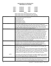
Temperature regulation valve If 120VAC is present on the electronic temperature
control, terminal #13 to neutral, check for voltage at
temperature regulation valve. If no voltage is present,
trace wiring back to electronic temperature control. If
voltage is present, listen for valve to open and close.
Also check for opens or shorts in the operating coil.
Replace temperature regulation valve as needed.
Intermittent heating Thermal/Overload of main fan
and burner blower motors
The main fan motor and burner blower motor are
equipped with internal thermal protection and will cease
to operate if overheating occurs. As the motors over-
heat and then cool, this will cause the units to cycle on
and off intermittently. Improper ventilation or lack of
preventive maintenance may cause this. Also, most of
the problems listed under “Oven will not heat” can
cause intermittent failure.
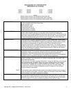
Conveyor will not run NOTE: The ovens may contain two, three or four conveyor drive systems using like
components. The trouble shooting sequence will be the same for each of the conveyor
drive systems
Power supply Check circuit breakers, reset if required. Check power
plug to be sure it is firmly in receptacle. Measure
incoming power, call power co. if needed.
Switch, oven fan Check continuity between switch terminals. Replace
switch as needed.
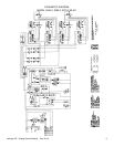
Relay, main fan Check for 120VAC supplied to relay terminal #13. If
voltage is not present, trace wiring back to power
supply. If voltage is present, check for 120VAC at
terminal #14. If there is no voltage at terminal #14, and
the relay is energized, replace the main fan relay.
Fuse, 2 Amp Check, replace if necessary.
Fuse holder Check for 120VAC supplied to fuse holder. If no voltage
is present, trace wiring back to main fan relay. Check
fuse holder, replace if necessary.
Switch, conveyor Check for 120VAC supplied to conveyor switch. If no
voltage is present, trace wiring back to fuse holder.
Check continuity between switch terminals. Replace
switch as needed.
Control, conveyor Check for 120VAC supplied to conveyor control at
terminals #1 (AC) and #2 (AC). If no voltage is present,
trace wiring back to conveyor switch. If AC voltage is
present, check for DC voltage output at terminals #3
(A-) and #4 (A+). If there is AC voltage in, but no DC
voltage out of the conveyor control. Replace the
conveyor control. If there is D.C. voltage output,
proceed.
Fuse, 2 Amp Check, replace if necessary.
Fuse holder Check for D.C. voltage supplied to fuse holder. If no
voltage is present, trace wiring back to conveyor
control. Check fuse holder, replace if necessary.
Switch, conveyor reversing Check for D.C. voltage supplied to the reversing switch.
If no voltage is present, trace wiring back to the fuse
holder. Check continuity between switch terminals.
Replace switch as needed.
Conveyor motor Check for D.C. voltage to the conveyor motor. If no
voltage is present, trace wiring back to the reversing
switch. If voltage is present and the motor will not run,
check the motor windings for opens or shorts. Check
motor brushes for excessive wear. Replace motor
brushes as needed.
If any of the above fails, replace conveyor motor.
Conveyor Check for any mechanical problems in the conveyor