


32
Installation & Operation Manual
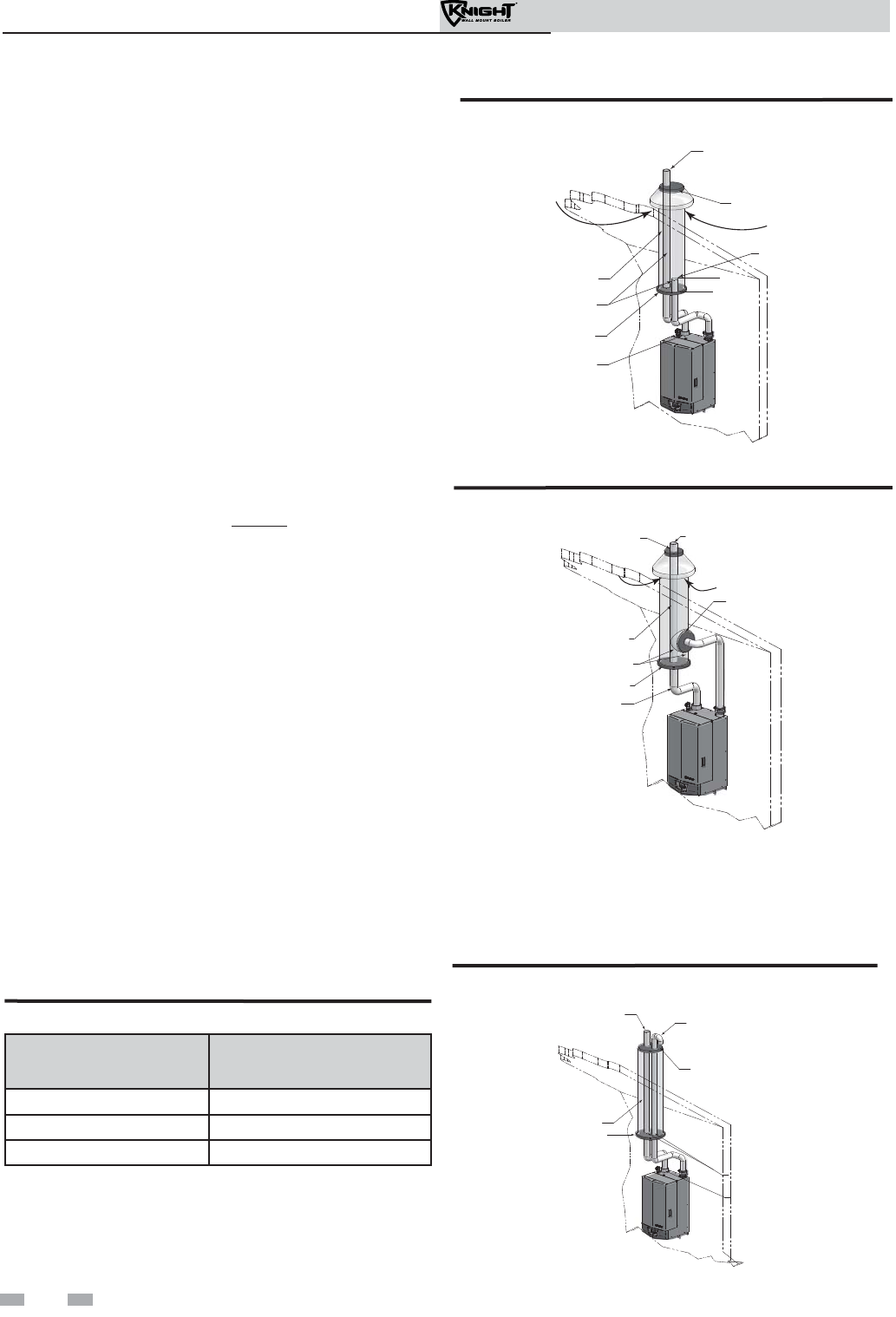
Alternate vertical concentric
venting
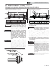
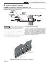
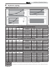
Vent / Air Inlet Size
Minimum Existing
Vent / Chase Size
2" 4"
3" 5"
4"
7"
Table 5A Alternate Vertical Concentric Vent / Chase Sizes
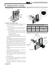
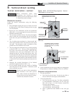
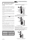
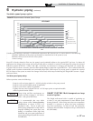
Figure 5-8 Concentric Vent Example 1
12”
MIN.
FLUE EXHAUST
SEAL
COMBUSTION AIR
FLUE OUTLET
SEALED
CAP
EXISTING
SEAL
AIR INLET
W/ SCREEN
*For concept illustration only. Individual installations
may vary due to job site specific equipment.
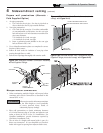
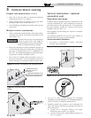
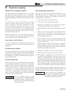
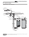
Figure 5-9 Concentric Vent Example 2
SEAL
COMBUSTION AIR
SEAL
FLUE OUTLET
SEALED
CAP
SEAL
EXISTING
FLUE EXHAUST
5 Vertical direct venting
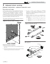
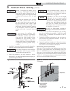
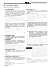
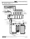
Figure 5-10 Existing Vent as a Chase
AIR INLET
FLUE EXHAUST
SEAL
CAP
EXISTING
SEAL
FLUE OUTLET
Existing vent as a chase
Follow all existing termination and clearance requirements and
allowable pipe lengths. Use only approved venting materials
listed in the General Venting Section of this manual.
*For concept illustration only. Individual installations may
vary due to job site specific equipment.
*For concept illustration only. Individual installations
may vary due to job site specific equipment.
This appliance may be installed with a concentric vent
arrangement where the vent pipe is routed through an
existing unused venting system; or by using the existing
unused venting system as a chase for vent and combustion
air routing.
Concentric Venting Arrangement
The venting is to be vertical through the roof. The annular
space between the O.D. of the vent pipe and the I.D. of the
existing unused venting system is utilized for the combustion
air source.
The minimum size of the existing vent system required to
achieve enough annular space for combustion air can be found
in Table 5A.
The upper and lower termination as well as any other unsealed
joints in the existing vent system must be sealed to ensure that
all combustion air is drawn from under the vent cap as shown
in FIG.’s 5-8 and 5-9.
Approved venting materials must be used as specified in Table
3D on page 19.
Follow all vent / air termination and clearance requirements
per this section to the appropriate example. Installation must
comply with local requirements and with the National Fuel
Gas Code.
The maximum allowable equivalent vent and air intake
lengths for this venting arrangement are to be determined
from the General Venting Section.
If an existing unused venting system is converted for use
with this method of concentric venting, the installer must
ensure that the existing venting system is clean and free from
particulate contamination that will harm this appliance and
cause increased nuisance calls or maintenance. See Table 1A
on page 10 for a list of corrosive contaminants and sources.
Two example scenarios of a concentric venting arrangement
are shown for illustrative purposes in FIG.’s 5-8 and 5-9.