Section 2 Installation Instructions
2-5
Water Service/Drains
WATER SUPPLY
Local water conditions may require treatment of the
water to inhibit scale formation, filter sediment, and
remove chlorine odor and taste.
Important
If you are installing a Manitowoc water filter
system, refer to the Installation Instructions
supplied with the filter system for ice making water
inlet connections.
Follow these guidelines to install water inlet lines:
• Connect to potable water supply only.
• Do not connect the ice machine to a hot water
supply. Be sure all hot water restrictors installed
for other equipment are working. (Check valves
on sink faucets, dishwashers, etc.)
• If water pressure exceeds the maximum
recommended pressure, obtain a water pressure
regulator from your Manitowoc distributor.
• Install a water shut-off valve for the ice making
water lines.
• Insulate water lines to prevent condensation.
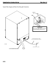
DRAIN CONNECTIONS
Follow these guidelines when installing drain lines to
prevent drain water from flowing back into the ice
machine and storage bin:
• Drain lines must have a 2.5 cm (1 inch) drop per
1 meter (40 inches) of run, and must not create
traps.
• The floor drain must be large enough to
accommodate drainage from all drains.
• Insulate the bin drain line to prevent
condensation.
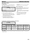
WATER SUPPLY AND DRAIN LINE SIZING/CONNECTIONS
CAUTION
Plumbing must conform to state and local codes.
Water
Temperature
Water
Pressure
Ice Machine
Connection
Tubing Size Up to Ice
Machine Fitting
Ice Making
Water Inlet
10°C (50°F) Min.
1
30°C (86°F) Max.
2
2.4 bar (35 psi) Min.
1
6.2 bar (90 psi) Max.
2
3/4” male hose
connection
3
0.95 cm (3/8”)
minimum inside
diameter
Ice Making/Bin
Water Drain
--- ---
1.59 cm (5/8”)
inside diameter
flexible hose
1.59 cm (5/8”)
minimum inside
diameter
1
Min. = Minimum
2
Max. = Maximum
3
A 3/4” by 11-1/2 threads per inch to 14 threads per inch adapter is factory installed. Remove this adapter if 11-1/2 threads per inch
connection is desired.


