


Section 6 Electrical System
Part Number 80-1634-3 6-3
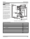
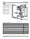
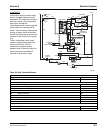
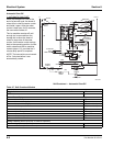
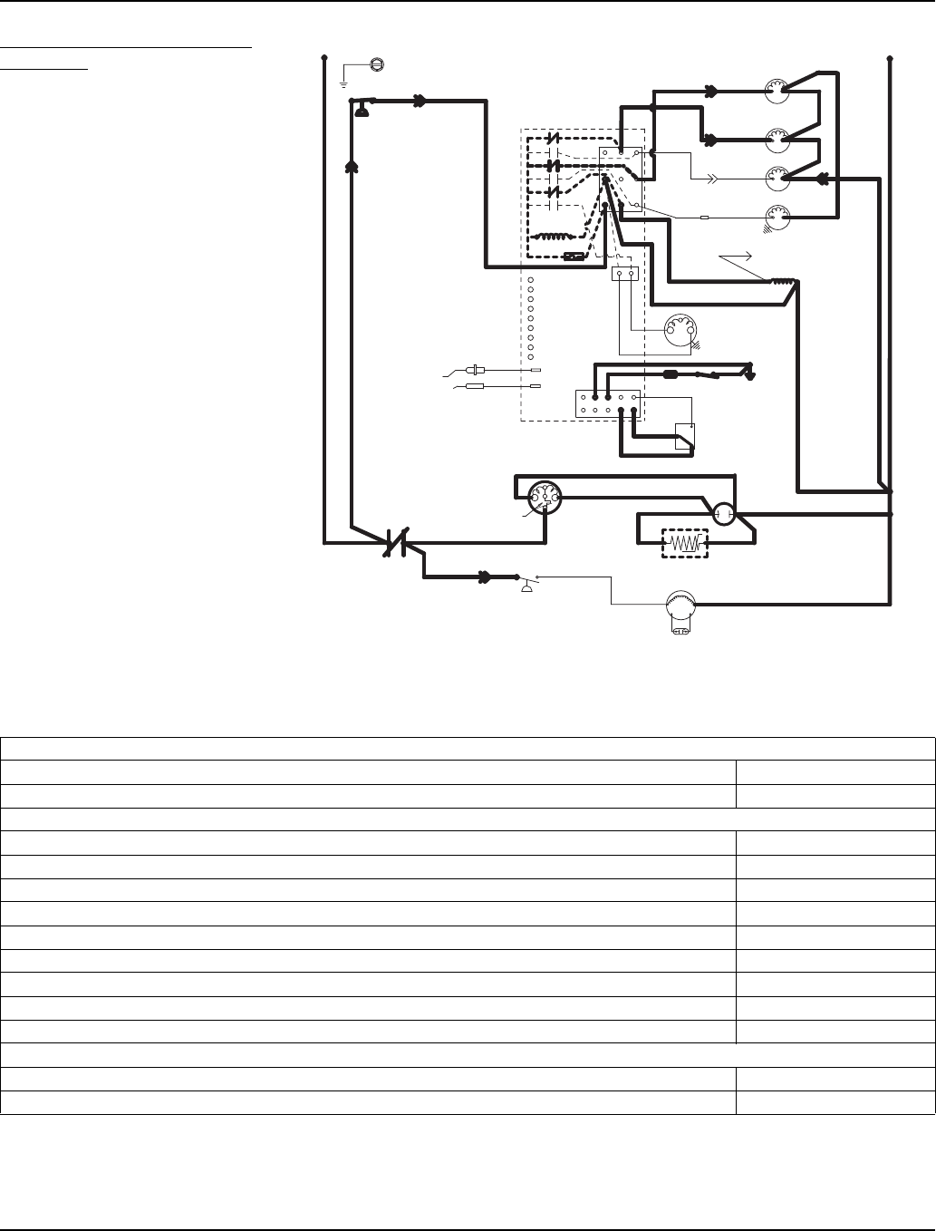
2. REFRIGERATION SYSTEM
START-UP
The compressor starts after the 45-
second water purge, and it remains
on throughout the Freeze and
Harvest cycles.
The water fill valve is energized at
the same time as the compressor.
The harvest valve(s) remains on for
the first 5 seconds of the initial
compressor start-up and then shuts
off.
At the same time the compressor
starts, the condenser fan motor (air-
cooled models) is supplied with
power throughout the entire freeze
and harvest sequences.
The fan motor is wired through a fan
cycle pressure control, and may
cycle on and off. (The compressor
and the condenser fan motor are
wired through the contactor. Any time
the contactor coil is energized, the
compressor and fan motor are
supplied with power.)
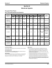
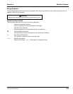
Self-Contained — Refrigeration System Start-Up
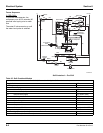
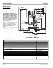
Table 6-2. Self-Contained Models
2. Refrigeration System Start Up (5 Seconds)
Toggle Switch ICE
Bin Switch Closed
Control Board Relays
#1 Water Pump OFF
#2 Harvest Valve (Left) ON
#3 Harvest Valve (Right) ON (When Used)
#4 Air Compressor ON (When Used)
#5 Water Inlet Valve ON
#6 Water Dump Valve OFF
#7 Contactor Coil Closed / ON
#7A Compressor ON
#7B Condenser Fan Motor OFF
Safety Controls (Which could stop ice machine operation)
High Pressure Cut-Out Closed
Main Fuse (On Control Board) Closed
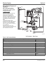
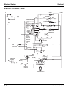
SV3137-4
(89)
(55)
(88)
High
Pressure
Cutout
Control Board
L1
Ground
(2)
(6)
(5)
(1)
(7)
(4)
L2 or N
Water Valve
Harvest Valve
(20)
(21)
(22)
(61)
Dump Valve
Water Pump
(60)
(76)
(81)
(75)
(77)
(80)
(57)
(98)
(58)
(59)
(42)
Ice Thickness
Probe
Water Level Probe
Trans.
Fuse (7a)
L2
Terminates at
Pin Connection
(99)
Contactor Coil
(56)
Air Compressor
(26)
(25)
Low DC
Voltage
Plug
Bin Switch
Clean
OFF
ICE
(2)
(1)
(6)
(8)
(9)
(74)
Compressor
Run Capacitor
(Red)
(Yellow)
Fan Motor
PTCR
(45)
(46)
(50)
(51)
(85)
Overload
(Black)
(86)
Fan Cycle
Control
L1
Contactor
Contacts
Run Capacitor