


GREEN
RED
WHITE
BLACK
RED
WHITE
BLACK
M
F
AMP PLUG
HI
LOW
SWITCH
HI SPEED
COMMON
LOW SPEED
EARTH
CAPACITOR
BLACK
BLACK
BLACK
BLACK
BLACK
GREEN
GND
BLACK
L1
(W) N
(B) L2
GREEN
RED
WHITE
BLACK
RED
WHITE
BLACK
M
F
AMP PLUG
HI
LOW
SWITCH
HI SPEED
COMMON
LOW SPEED
EARTH
PURPLE
WHITE
BLUE
GREEN
GND
BLACK
L1
(W) N
(B) L2
MOTOR
MOTOR
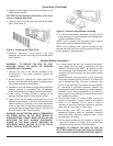
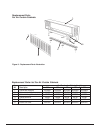
Installation
1. Using template provided, determine mounting
location.
2. Drill holes and attach mounting hardware (not
included).
IMPORTANT: THE HARDWARE AND THE
SUPPORTING STRUCTURE MUST BE CAPABLE OF
SUPPORTING A MINIMUM 150 LB. LOAD.
NOTE: All installation should be done to meet local
building code.
3. Mount cabinet on wall and securely tighten hardware.
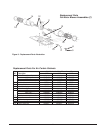
4. Replace motor/blower assembly in cabinet. Secure
two wing nuts on blower base. Reconnect motor
electric cord plug assembly.
5. Replace intake grille with louvers facing down and
refasten knurled nuts.
ELECTRICAL CONNECTIONS
WARNING: ALL AIR CURTAINS SHOULD BE
INSTALLED BY QUALIFIED PERSONNEL.
1. Connect motor per nameplate to correct power supply.
Use adequate size wire for all branch and feeder runs.
2. Install all wiring, protection and grounding in
accordance with the National Electrical Code (NEC)
and all local requirements.
WARNING: THIS FAN HAS AN INTERNAL SELF
RESETTING THERMAL OVERLOAD PROTECTOR.
ALWAYS DISCONNECT FROM POWER SUPPLY
BEFORE SERVICING.
3. Remove two screws from switch box and remove
cover.
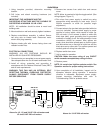
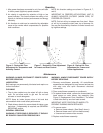
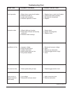
NOTE: Motor is prewired to high/low toggle switch. (See
wiring diagram, Figure 5.)
4. Run wires from power supply to switch box using
appropriate wiring according to local code. (Use a
flexible connector to allow for possible angle
adjustment.)
5. Connect wires to the two lead wires provided with wire
nuts (not included). Connect black supply to center
terminal of rocker switch, white neutral to white (for
220 volt units, L2 will connect to black or white with
black tape lead), green grounding lead to grounded
conductor of supply circuit. No loose strands or loose
connections should be present. After splices are
made, wires should be spread apart so that the green
and white wires are on one side of outlet box and the
black wires are on other side. Turn splices upward and
carefully push all wiring into outlet box.
6. Replace switch box cover.
7. Unit is ready for operation.
CAUTION: Make sure amp rating of any ON/OFF
switch exceeds nameplate amp rating of motor.
8. Restore power.
NOTE: Air curtain has high/low selector switch. See
Operation section for proper setting instructions.
9. Upon completion of all installation, inspect unit for
excessive vibration during operation. If excessive
vibration is noticeable, disconnect power supply.
Inspect mounting installation and refer to
Troubleshooting Chart for probable cause.
Above for 1/4, 1/2 and 3/4 HP 120 volt motors and
1/2 and 3/4 HP 220 volt motors.
Above for 1/4 HP 220 volt motor.
3