


13
FINAL CHECK LIST
A. Check operating pressures.
B. Check electrical requirements of unit to supply voltage.
C. Set temperature control for desired temperature range.
D. Check system for proper defrost settings and operation.
E. Check condensing unit for vibrating or rubbing tubing. Dampen and clamp as required.
F. All valves should be completely open counter-clockwise.
G. Check packing nuts on all service valves.
H. Replace all service valve caps and latch unit covers.
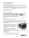
SENSOR PROBE
NOTICE: If the probe assembly is disconnected from the main board during normal operation (unit running),
the connectors must be installed in the same position that they had before disconnection (P1 and P2),
otherwise the control will not function properly.
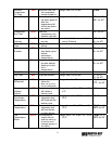
The Electronic Refrigeration Control sensors have NTC thermistors. The reference resistance is 30,000
ohms at 77°F (25°C). It carries NTC thermistors with a range of –40° to 199° F. In case there is a failure,
these sensors should be used in replacement of the sensors shipped with the control. In order to diagnose
faults in the probe, the control has LED functions as a diagnostic tool. When power is supplied to the control,
the LED will turn on and will remain on as long as this condition is satisfied. When there is a fault in the probe,
the LED will blink intermittently. When this occurs, the probe assembly needs to be replaced. If power is
supplied to the control and the LED remains off, there is a failure in the main relay control and it needs to be
replaced.
In case of a probe failure, the control will go into a safety mode of operation. While in safety mode the control
ignores probe inputs and cycles the compressor on for 5 minutes and off for 3 hours. The LED will be blinking
and signaling that there is something wrong with the probe. To replace the sensor probes, disconnect power
to the control, replace the probes and restart the unit. Since the wire is fixed to the cabinet, a technician may
cut the sensor wire inside the cabinet and splice it with a new sensor.
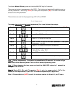
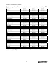
SENSOR PROBE TEMPERATURE AND RESISTANCE
Temperature Resistance
°F °C
Ohms
-29.2 -34 683,100
-20.2 -29 499,200
-9.4 -23 347,100
-0.4 -18 259,500
10.4 -12 185,200
19.4 -7 141,200
30.2 -1 103,100
32.0 0 97,950
39.2 4 80,040
50.0 10 59,700
60.8 16 45,000
69.8 21 35,820
80.6 27 27,500
89.6 32 22,210