


Component Testing Procedures
!
WARNI NG
To avoid electrical shock, personal injury, or death: disconnect power supply before servicing, unless testing
requires it.
©2003 Maytag Appliances Company 16022159 Rev. 0
9
Power Supply
If no part of the cooktop operates or only part of it
operates, the cause may be a problem in the power
supply.
1. Verify supply circuit breakers or fuses are not tripped.
Check rating.
2. Disconnect power source. Check terminals at
terminal block for tightness.
3. Verify cooktop service wires are properly connected.
Be sure wires are in good condition. Check for proper
voltage with a voltmeter.
Internal Wiring
1. Disconnect power from cooktop.
2. Place one ohmmeter lead at the terminal block.
Place the other lead at the line terminal of the
non−functioning part. Meter should indicate
continuity.
Use the appropriate wiring diagram to repeat this
procedure from the output of the control to the next point
until each wire section is checked. Often a visual check
of the wiring will determine where a wiring fault is.
Indicator Light
1. If the surface unit operates normally but the indicator
lights do not glow, check for voltage at the indicator
light terminals.
2. If voltage is present at the indicator terminals and the
indicator does not glow, replace the indicator light.
3. If no voltage is present at the terminals, check for
loose connections or broken wiring.
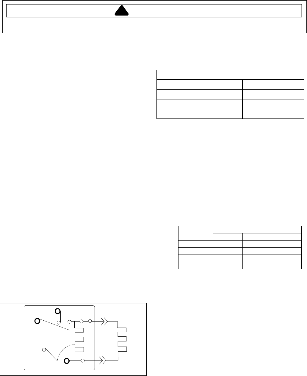
Warming Element (Infinite Switch)
Power Connection
1. See schematic diagrams for assistance in testing
voltages in and out of control.
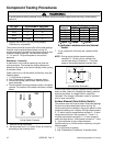
2. Connect a voltmeter to the element or the terminals
H1 and H2 of the surface warming control.
L1
P1
H1
H2
L2
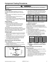
3. Turn control to LOW setting and allow it to cycle
approximately two minutes. Time the OFF and ON
cycle of the control and compare to the following
table based on a 60 second cycle.
SETTING APPROXIMATE SECONDS
TIME ON OFF
LOW 4 56
421 39
HIGH Constant 0
4. Replace the control if it is not cycling properly.
Calibration is not possible.
Resistance / Continuity
A malfunction in the internal switching may fuse the
cycling contacts. This causes the heating element to
operate at full power, at all control settings, while cycling
on element limiter.
1. Disconnect power from cooktop.
2. See “Disassembly Procedure“ to access switch.
3. Connect voltmeter test lead to H1 and H2 terminals.
4. Connect appliance to power source.
5. Set control to any setting. Meter should indicate
120 VAC volts. After allotted ON cycle, contacts
should cycle open and indicate 0 VAC.
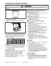
Dial Position
Contacts OFF LO-MED HI
L1 – P O X X
L1 – H1 O X X
L1 – H2 O X – C X
H1–H2 X E X
O−Open X−Closed C−Cycles
E−Indicates resistance across internal
heater
Surface Elements (Infinite Switch)
Power Connection
1. See schematic diagrams for assistance in testing
voltages in and out of control.
2. Connect a voltmeter to the element or the terminals
H1 and H2 of the surface control.
3. Turn control to LOW setting and allow it to cycle
approximately two minutes. Time the OFF and ON
cycle of the control and compare these to the
following table.