


©2003 Maytag Appliances Company 16022159 Rev. 0 13
Disassembly Procedures
!
WARNING
To avoid risk of electrical shock, personal injury or death, disconnect power to cooktop before servicing, unless
testing requires power.
Disassembly Procedures for Models Listed
• JEC8430ADB/W/F/N/S
• JEC8536ADB/W/F/N/S
• MEC5430BDB/W/S
• MEC5536BAB/W/S
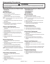
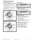
Main Top Removal
1. Disconnect power to cooktop.
2. Remove knobs from valve stems.
NOTE: To remove knob(s), slide a rag under the knob
and pull upward.
3. Remove cooktop from installation position and place
face down on protected surface.
4. Remove screws securing main top to burner box
bottom.
5. Remove screws securing control panel box and
conduit mounting plate to burner box assembly.
NOTE: Control panel box screws are located in front
center and conduit mounting plate screws are
located in rear left.
6. Remove main top.
NOTE: Make sure the pieces of insulation, located in
the front left and right rear corners, are put back
in place. Failure to do so could create
excessive cabinet temperatures.
7. Reverse procedure to reassemble, verifying that
cooktop frame is properly aligned.
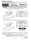
Element Replacement
1. Remove main top, see "Main Top Removal"
procedure.
2. Remove screws securing element clips to main top.
NOTE: Element clips are positioned at numbered
locations. If element clips are removed from
element, note the locations prior to removal.
3. Disconnect and label wiring to element.
4. Replace element and reverse procedure to reinstall.
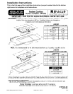
Infinite Switch Replacement
1. Remove main top, see "Main Top Removal"
procedure.
2. Remove screws securing switch-mounting plate to
main top.
NOTE: An access panel is provided on the bottom of
the burner box for component diagnosis.
3. Lift plate to gain access to switch mounting screws.
4. Remove screws securing switch to mounting plate
and remove switch.
5. Disconnect and label wiring to infinite switch.
6. Replace infinite switch and reverse procedure to
reinstall.
Indicator Light Replacement
1. Remove main top, see "Main Top Removal"
procedure.
2. Remove screws securing mounting plate to main top.
3. Lift plate to gain access to indicator light.
4. Depress tabs securing indicator light to mounting
plate.
5. Disconnect and label wiring to indicator light.
6. Replace indicator light and reverse procedure to
reinstall.
Disassembly Procedures for Models Listed
• JEC9530ADB/F/S
• JEC9536ADB/F/S
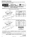
Main Top Removal
1. Disconnect power to cooktop.
2. Remove knobs from valve stems.
NOTE: To remove knob(s), slide a rag under the knob
and pull upward.
3. Remove cooktop from installation position and place
face down on protected surface.
4. Remove screws securing main top to burner box
bottom.
5. Remove screws securing conduit mounting plate to
burner box assembly.
NOTE: Conduit mounting plate screws are located in
rear left corner.
6. Remove main top.
NOTE: Make sure the pieces of insulation, located in
the front left and right rear corners, are put back
in place. Failure to do so could create
excessive cabinet temperatures.
7. Reverse procedure to reassemble, verifying that
cooktop frame is properly aligned.
Element Replacement
1. Remove main top, see "Main Top Removal"
procedure.
2. Remove screws securing element clips to main top.
NOTE: Element clips are positioned at numbered
locations. If element clips are removed from
element, note the locations prior to removal.
3. Disconnect and label wiring to element.
4. Replace element and reverse procedure to reinstall.