


©2004 Maytag Services 16023522 A– 10
Installation Instructions (All models except CPL1100AD*,
CGL1100AD*, CP31200AD*, CG31200AD*, LPR1115AD*)
-6-
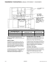
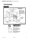
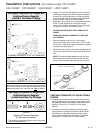
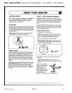
*DV 6XSSO\ &RQQHFWLRQ )RU 5DQJHV :LWK
$SSOLDQFH 3UHVVXUH 5HJXODWRU
/RFDWHG 8QGHU 0DLQ 7RS 2I 5DQJH
cfdrob Q
Appliance Pressure Regulator
& Alternate Connectors
The appliance pressure regulator on your range may
differ from this illustration.
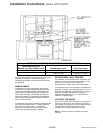
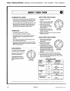
*DV 6XSSO\ &RQQHFWLRQV )RU 5DQJHV :LWK
$SSOLDQFH 3UHVVXUH 5HJXODWRU
/RFDWHG ,Q 7KH %RWWRP 2I 5DQJH
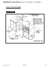
WHEN THE INSTALLER HAS COMPLETED INSTALLATION
OF THE APPLIANCE, LEAVE THE APPLIANCE PRESSURE
REGULATOR SHUT-OFF VALVE IN THE
POSITION.
72 &211(&7 *$6 6833/< 72 2 137 0$/( ,1/(7
72 &211(&7 *$6 6833/< 72 2 137 )(0$/( ,1/(7
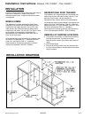
h. Apply a non-corrosive leak detection fluid to all joints
and fittings in the gas connection between the supply
line shut-off valve and the range. Include gas fittings
and joints in the range if connections were disturbed
during installation. Check for leaks! Bubbles
appearing around fittings and connections will indicate
a leak. If a leak appears, turn off supply line gas
shut-off valve, tighten connections, turn on the supply
line gas shut off valve, and retest for leaks.
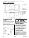
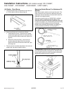
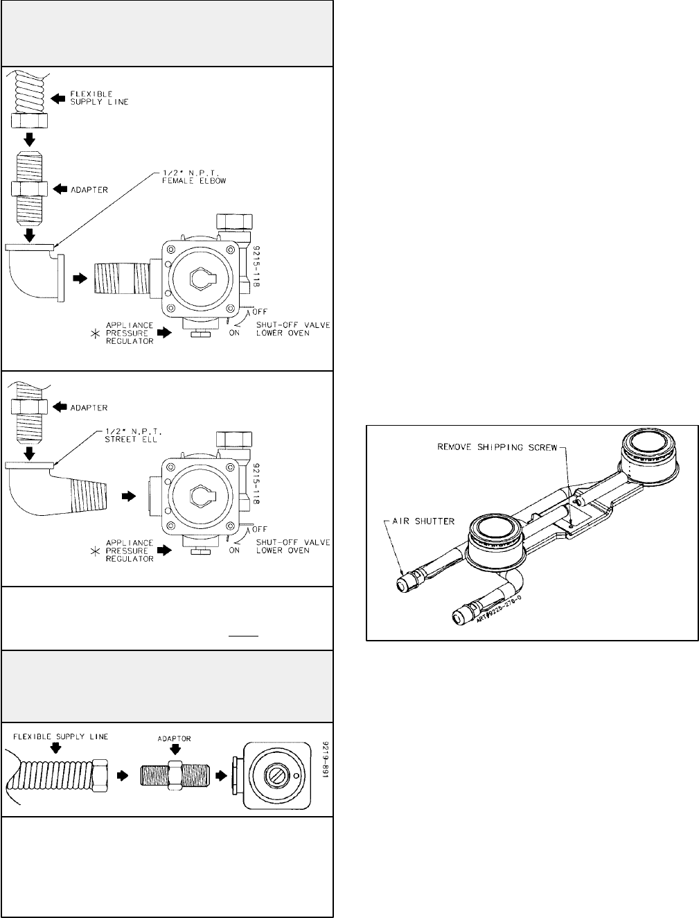
i. Remove shipping screw from ALL top burners.
(Conventional top burner models only). This is to hold
the burners in place on the burner bracket for shipping
purposes only. (See figure 5).
j. Adjust burner air shutter to the widest opening that will
not cause the flame to lift or blow off the burner when
cold.
Correctly adjusted sealed burners, can have
flames that will lift or blow off without a pot over the
burner. These should be adjusted with a pot in place.
cfdrob R
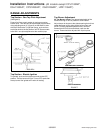
3. The appliance and its individual shutoff valve must be
disconnected from the gas supply piping system during
any pressure testing of that system at test pressures in
excess of 1/2 lbs./sq. in. (3.5 kPa) (13.8 in. water
column).
4. The appliance must be isolated from the gas supply
piping system by closing its individual manual shutoff
valve during any pressure testing of the gas supply
piping system at test pressures equal to or less than
1/2 lbs./sq. in. (3.5 kPa) (13.8 in. water column).