


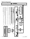

Electrical Diagnostics
!
WARNING
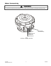
To avoid risk of electrical shock, personal injury, or death, disconnect power to dishwasher before servicing.
16026393 6 July 2005
©2005 Maytag Services
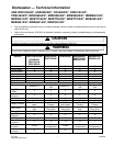
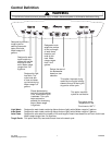
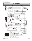
Pin#12345678 Pin#1234 StakeLug11109876 54321
OR RD RD AQ PU BK PU TN AQ
WH WH
YL GY BU BK BK RD
BK
Circuit Board
Heater
(14.5 - 16.5**)
(High limit t'stat must
be closed)
3
2
A
lways
remove power to the unit
before performing any resistance or
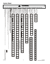
continuity checks.
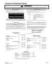
Resistance Check Points and Values
Disp. WM
(2K**)
J5 J6
*Vent WM
(1.2K**)
Thermistor (thru harness only with
connector unplugged)***
10K* +/- 3% @ 77
o
F
2.4K* +/- 6.5% @ 140
o
F
*** A resistor in the control board wired in parallel will result in an approximate reading of 4.0 k ohms
with connector J5 plugged in.
** Nominal value for ohms of electrical resistance of component only. These values will vary slightly
due to the additional resistance of the wire harness. Greater variation can occur if the component is
still warm from being energized during testing.
Drain Motor
(25**)
1
Wash Motor
(3 - 4**)
Water Valve
(1.1K**)
(float switch
must be closed)
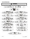
Use the "Manual Function Test" as described on the electrical schematic sheet to
check components before
opening the door to perform continuity testing or replacing parts.
To check continuity from ends of power leads to control board through door switches
(A white plastic latch must be inserted in the latch assembly for this test.)
> With one ohm meter lead connected to the white (neutral) power lead, you should have continuity at
stake lugs 10 & 11.
> With one ohm meter lead connected to the black (line) power lead, you should have continuity at
stake lugs 3 & 4, and pin # 8 on connector J5.
Perform the resistance checks on the component(s) in question at the locations shown on the chart.
* Select Models Only.