


25
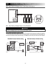
9.0
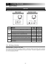
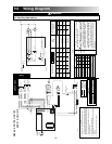
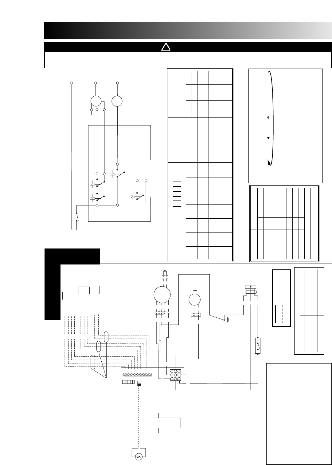
Wiring Diagram
A1
M1
M2
K1
RELAY
K2
RELAY
K5
RELAY
FAN
MOTOR
DAMPER
MOTOR
NEUTRAL
MED
NC
HIGH
LOW
J1 6
J1 3
J1 4
J1 9
K4
RELAY
J3 1
J3 2
FURNACE BLOWER INTERLOCK
CLASS 2 CIRCUIT ONLY
ELECTRONIC ASSEMBLY
S1
120V 60Hz
FROM MAIN
J1 2
J1 1
J1 8
VE0018A
BK
G
R
Y
R
BK
Y
NOTE 4
WALL CONTROL
WALL CONTROL
WALL CONTROL
WALL CONTROL
OVERRIDE SWITCH
OVERRIDE SWITCH
OVERRIDE LED
FURNACE BLOWER
INTERLOCK
NOTES 1, 5
NOTE 5
OPTIONAL
NOTES 5, 6
OPTIONAL
M1
X2
M2
1
2
1
123
12
4
7
6
9
3
456789
2
3
1
2
NEUTRAL
MEDIUM
HIGH
LOW
FAN MOTOR
X1
GY
O
G
BL
R
GY
O
G
NC
R
(NOTE 2)
BN
BN
C1
BL
BL
DAMPER
MOTOR
MAIN EARTHING
POINT
R
O
GY
W
T1
R1
A1
DEFROST
TEMPERATURE
SENSOR
JU1
J4
J1
J3
ABCDEFG
FFIOCOLYRGB
ELECTRONIC ASSEMBLY
Y
BL
BL
Y
COM
120V 60 Hz
W1
G
BK
W
NEMA-15P
5-15 PLUG
BK
DOOR INTERLOCK
SWITCH S1
NO
NEUTRAL
LINE
BK
VE0037A
-t°
Models: ERV-150, HRV-150,
ERV-210, HRV-210
NOTES
1- Controls available. See Section 8.0 (Low voltage only, 12VDC)
2- The factory set wiring for blower speed selection is high and low.
Medium speed can be selected instead of low speed. Disconnect the
RED wire from the motor RED tap and connect it to the motor BLUE tap.
3- If any of the original wire, as supplied, must be replaced, use the
same or equivalent wire.
4- Use the factory supplied protective tubing.
5- The field wiring must comply with applicable codes, ordonnances and
regulations.
6- The furnace fan circuit must be class 2 circuit only.
LINE VOLTAGE
LOW VOLTAGE AND
FIELD WIRE
COLOR CODE
BK BLACK NC NO CONNECTION
BL BLUE O ORANGE
BN BROWN R RED
G GREEN W WHITE
GY GREY Y YELLOW
DEFROST TIME
JUMPERS TABLE MODEL MODEL DEFROST/VENTILATION
TYPES MINUTES
23°F 5°F -17°F
JU1A JU1B JU1C JU1D JU1E JU1F JU1G -5°C -15°C -27°C
OUT OUT IN IN OUT IN OUT
HRV-150
6/32 6/32 6/20
HRV-210
OUT IN OUT IN OUT IN OUT
ERV-150
6/32 NOTE NOTE
ERV-210
NO NO NO NO NO
OUT
NO EXTENDED DEFROST
10/30 10/20 10/15
CHANGE CHANGE CHANGE CHANGE CHANGE CHANGE HRV ONLY
Connection
Logic
A B C D E F G
2
1
JU 1
. .
. .
. .
. .
. .
. .
. .
FUNCTION TABLE RELAY
MODE K1 K2 K4 K5
Intermittent 0 0 0 0
Exchange Low 1 0 1 1
Exchange High 1 1 1 1
Circulation Low 1 0 1 0
Circulation High 1 1 1 0
Defrost Cycle 1 1 1 0
Off 0 0 0 0
0 = Relay coil is de-energized
1 = Relay coil is energized
SPECIAL DEFROST CYCLE:
The mode is the same whichever the exchange
speed selected by the wall control.
6 min. defrost 34 min. OFF 20 min. exchange low speed
BELOW
-15°C - Achange of air exchange speed on the wall control
(-5°F) during the special defrost cycle will reset the special
defrost cycle to the beginning (6 min. defrost).
- The override circuit will remain active during the
special defrost cycle. An override call will be answered.
- If the outside temperature revert above -15°C (5°F),
it is only during the last part of the cycle (20 min.
exchange) that the controller will stop the special
defrost cycle.
NOTE
WARNING
010
!
Risk of electrical shocks. Before performing any maintenance or servicing, always disconnect the
unit from its power source.