


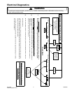
Component Readings/Testing
!
WARNING
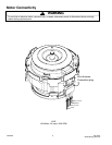
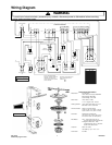
To avoid risk of electrical shock, personal injury, or death, disconnect power to dishwasher before servicing,
unless testing requires power.
16023063 4 May 2004
©2004 Maytag Services
Manual Function Test
A Manual Function Test may be started by pressing the key
5 times followed by the key within 6 seconds.
Normal Wash
Start
The LED will 3 times indicating manual test mode is
active. Specific keypads will turn on or off a component as follows:
Wash Motor
Drain Motor
Water Valve
Soap Dispenser (cycle once)
Rinse Aid (cycle twice)
Vent
Heating Element
When a component is activated by pressing a specific keypad, the LED above
the keypad will be . The test will cancel 120 seconds after the last keypad is
pressed. The display (if available) will show ‘99’ until the remaining timeout
period is less than 99 seconds. At this point it will countdown until the mode
times out, is cancelled, or another key is pressed. To cancel test, press the
keypad.
Press keypad 5 times within 6 seconds. The LEDs will illuminate
in a progressive order until all are lit. All LED’s will stay on for 1 second then all
go off simultaneously. The display (if available) will begin at ‘50’ and sequence
down to ‘0’ at a 1 second interval and repeat until this mode is terminated. This
mode will repeat.
To cancel, press the keypad.
To check control LEDs, enter . If control fails to
perform as described, replace control. To check control and components, enter
. If control fails to perform sequence as described, and a
fault is detected, determine failure as described in the . If a
load component failure has been diagnosed, proceed to the
. To check individual load components for proper operation, enter
. Follow test procedure as described. Repair or replace
component as needed.
: The or may be detected during
a wash cycle selected by a consumer. If this happens, the control will go into a
30 second auto restart mode and shut down if the unit is not able to restart the
motor.
Normal Wash Flash
Heavy Wash
Normal Wash
Light Wash
Rinse Only
Sanitize
Heated Dry
On
Start / Cancel
Extra Rinse
Start / Cancel
Sales Floor Demo Mode
Field Service Test
Field Service Test
Manual Function
Test Manual
Function Test
Note High Current Low Current Motor Error
Sales Floor Demo Mode
Diagnostic Tips
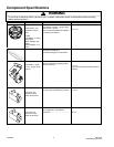
Membrane Readings
(Front Only Controls)
Heavy Wash
Normal Wash
Light Wash
Rinse Only
Auto Clean
Start / Cancel
Delay
Heated Dry
Sanitize
Tough Scrub
Tough Scrub Plus
Extra Rinse
Model ID Jumper
An unpressed switch will read as an open circuit.
A pressed switch will read as 10 k ohms.
* On select models
*
Connector
J1
J1
J1
J1
J1
J1
J1
J1
J1
J1
J1
J1
J1
Measure Between
Pin 9 - Pin 5
Pin 9 - Pin 6
Pin 9 - Pin 7
Pin 9 - Pin 8
Pin 10 - Pin 5
Pin 10 - Pin 6
Pin 10 - Pin 7
Pin 11 - Pin 5
Pin 11 - Pin 6
Pin 11 - Pin 7
Pin 10 - Pin 8
Pin 11 - Pin 8
Pin 12 - Pin 7
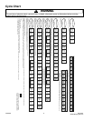
Field Service Test
A Field Service Test may be started by pressing the key 5 times
followed by the key within 6 seconds. This test must be performed with
clean water to insure proper sensor performance.
“88” will appear in the display (if available*) and the following sequence of
events will occur:
Time frame for Thermistor/Turbidity Sensor check & calibration may vary
slightly.
The Field Service Test will not repeat. The LED will during
the test mode. Indicator lights (except and the Display) will
illuminate per Sales Floor Demo Mode. If the dishwasher door is opened
during the test, the test sequence will pause, and resume when the door is
closed. To the cancel test, press the keypad.
The control has been designed to test the Sensor Memory and Motor. During
the Field Service Test, if a fault has been detected, the test will abort any time
after the motor current has been checked and 2 or more LED's will begin to
. A will occur immediately after the test is
started. The LED and one of the following:
- failure - LED
- failure - LED
- high current - LED
- low current - LED
- LED
* On select models
** On units with Front Controls only, this will be the LED on units with
Top & Front Controls, this will be the LED
Heavy Wash
Start
Heavy Wash Flash
Heavy Wash
Start / Cancel
Flash Memory / Software Check
(See Note )
Turbidity Sensor Rinse Only
Thermistor Heavy Wash
Motor Normal Wash
Motor Light Wash
Memory Failure Heated Dry
Clean ,
Delay
**
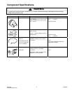
Membrane Readings
(Front & Top Controls)
SECONDS
106
5
120
180
120
4
FUNCTIONS / ACTIVE LOADS
Vent Wax Motor/Water Valve
Thermistor check/Turbidity Sensor check &
calibration - no loads active.
Wash Motor/Vent Wax Motor/Dispenser Wax Motor
Wash Motor/Heater/Vent Wax Motor
Drain Pump
Water Valve
Auto Clean
Heavy Wash
Normal Wash
Light Wash
Rinse Only
Quick Wash
Heated Dry
Sanitize
Extra Rinse
Tough Scrub Plus
160° Wash
Model ID Jumper
Start / Cancel
Delay
An unpressed switch will read as an open circuit.
A pressed switch will read as 10 k ohms.
* On select models
*
Connector
J1
J1
J1
J1
J1
J1
J1
J1
J1
J1
J1
J1
J3
J3
Measure Between
Pin 10 - Pin 5
Pin 9 - Pin 5
Pin 9 - Pin 6
Pin 9 - Pin 7
Pin 9 - Pin 8
Pin 10 - Pin 6
Pin 11 - Pin 5
Pin 11 - Pin 6
Pin 11 - Pin 8
Pin 10 - Pin 7
Pin 10 - Pin 8
Pin 12 - Pin 8
Pin 9 - Pin 5
Pin 9 - Pin 6
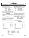
Heater¹
Wash Motor
Drain Motor
Vent Wax Motor
Dispenser Wax Motor
Water Valve²
Thermistor
1. This value assumes the high limit thermostat is closed.
2. This value assumes the float switch is closed.
3. Results are approximate values.
Notes:
Load Readings
Measure between:
ST1 (Heater) - ST11 (Dlb Neutral)
ST5 (Motor Common) - ST8 (Motor Main)
ST6 (Drain) - ST4 (Dlb Line)
J6 Pin 1 (Vent) - ST4 (Dlb Line)
J6 Pin 3 (Disp) - ST4 (Dlb Line)
J6 Pin 4 (Inlt) - ST4 (Dlb Line)
J5 Pin 1 (Temp) - J5 Pin 4 (Neutral)
Result
16 ohms
3 to 4 ohms
25 ohms
1.2 k ohms
2 k ohms
1.1 k ohms
See Component Info