


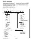

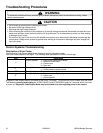
Testing Procedures
!
WARNING
To avoid risk of electrical shock, personal injury or death; disconnect power to oven before servicing, unless
testing requires power.
©2004 Maytag Services 16023416 15
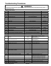
Component Testing
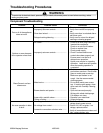
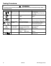
Illustration Component Test Procedure Results
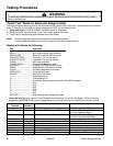
Oven light socket Remove one wire from receptacle and
test resistance of terminals..................
Measure voltage at oven light ..............
Indicates continuity with bulb screwed in.
120 VAC, see wiring diagram for terminal
identification.
If no voltage is present at oven light,
check wiring or light switches.
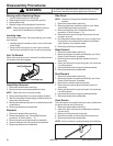
4-turn
5-turn
(Model MER6555AA*)
Coil elements Remove element and measure
resistance across terminals. ................
Continuity, if not replace.
4-turn: 37 to 45 Ω Approximately
5-turn: 23 to 27 Ω Approximately
1200 W
2500 W
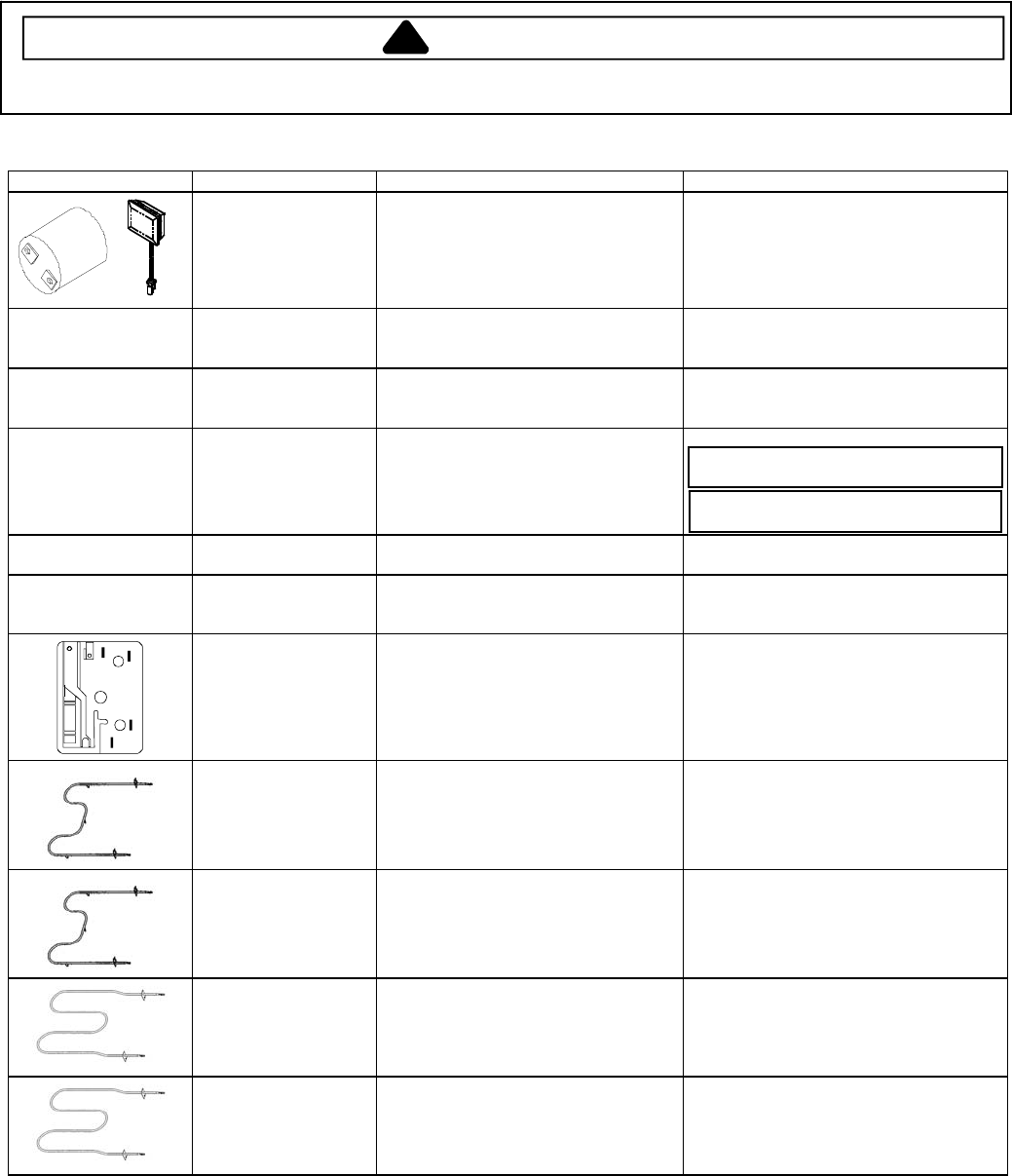
Ribbon elements Remove element and measure
resistance across terminals. ................
Continuity. If not, replace.
1200W: 45 to 49 Ω Approximately
2500W: 20 to 24 Ω Approximately
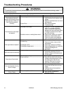
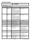
2400 W/1100 W (Dual)
2700 W/1700 W (Dual)
(Models MER6775AA*,
MER6875AA*)
Ribbon elements Remove element and measure
resistance across terminals. ................
Continuity. If not, replace.
1100W: 40 to 46 Ω Approximately (Inner)
1300W: 47 to 54 Ω Approximately (Outer)
1700W: 30 to 36 Ω Approximately (Inner)
1000W: 53 to 59 Ω Approximately (Outer)
2700 W (Single)
(Model MER6755AA*)
Ribbon elements Remove element and measure
resistance across terminals. ................
Continuity. If not, replace.
2700W: 19 to 23 Ω Approximately
100 W (Warmer)
(Models MER6775AA*,
MER6875AA*)
Ribbon elements Remove element and measure
resistance across terminals. ................
Continuity. If not, replace.
100W: 132 to 146 Ω Approximately
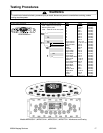
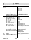
L2
L1
H2
P
H1
1
2
3
4
5
Snap Action Infinite
switch
Connect Volt-ohms meter to
H1 and H2.
Measure the following for voltages at
LO, MED, HI:
H1 to H2 ............................................
Approximate
Time On Time Off
LO 5% 95%
MED (4-5) 35% 65%
HI 100% 0%
240 VAC, if not replace switch.
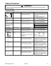
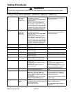
Bake element, Upper Disconnect wire leads to element and
measure resistance of terminals..........
Measure voltage at bake element ........
Approximately 31.0
Ω, if not replace.
240 VAC, see wiring diagram for terminal
identification. If no voltage is present at
bake element check wiring.
Bake element, Lower Disconnect wire leads to element and
measure resistance of terminals..........
Measure voltage at bake element ........
Approximately 21.3
Ω, if not replace.
240 VAC, see wiring diagram for terminal
identification. If no voltage is present at
bake element check wiring.
Broil element, Upper Disconnect wire leads to element and
measure resistance of terminals..........
Measure voltage at broil element .........
Approximately 25.4
Ω, if not replace.
240 VAC, see wiring diagram for terminal
identification. If no voltage is present at
broil element check wiring.
Broil element, Lower Disconnect wire leads to element and
measure resistance of terminals..........
Measure voltage at broil element .........
Approximately 18.6
Ω, if not replace.
240 VAC, see wiring diagram for terminal
identification. If no voltage is present at
broil element check wiring.