


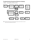
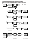
Testing Procedures
!
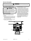
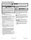
WARNI NG
To avoid risk of electrical shock, personal injury or death; disconnect power to oven and discharge capacitor
before servicing, unless testing requires power.
©2004 Maytag Services 16023293 Rev. 0
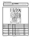
23
TAB 1
TAB 2
RLY 3
19
3
54
8
C1N
12
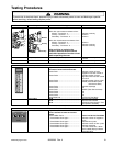
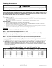
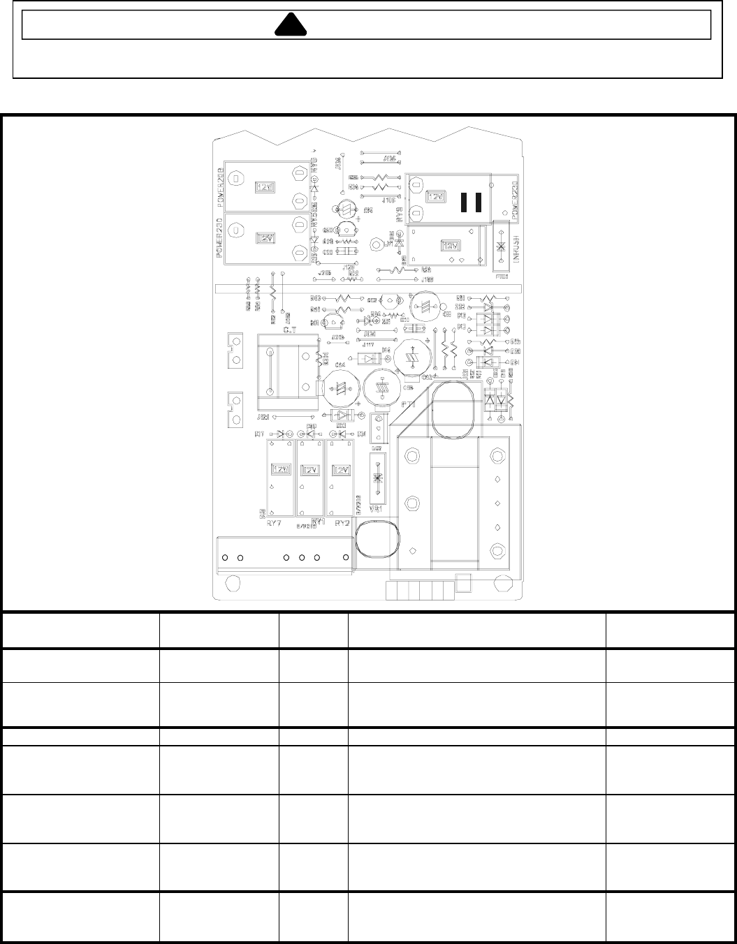
Function Test Set-Up /
Condition
Meter
Setting
Probe Placement Results
Power to current
transformer
All Conditions Volts Tab 1 to CN1 Pin 3 (Neutral) 120 VAC
Power from current
transformer
All Conditions Volts Tab 2 to CN1 Pin 3 (Neutral) 120 VAC
Power from Oven TCO All Conditions Volts CN1 – Pin 1 (Black wire to Neutral) 120 VAC
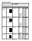
Power to Oven Light Standby.............
Ready................
Cook .................
Volts
Volts
Volts
CN1 – Pin 4 to Pin 1 .............................
CN1 – Pin 4 to Pin 1 .............................
CN1 – Pin 4 to Pin 1 .............................
120 VAC
0 VAC
0 VAC
Power to Blower Motor Standby.............
Ready................
Cook .................
Volts
Volts
Volts
CN1 – Pin 5 to Pin 1 .............................
CN1 – Pin 5 to Pin 1 .............................
CN1 – Pin 5 to Pin 1 .............................
120 VAC
0 VAC
0 VAC
Secondary Interlock
Switch
Door Closed......
Door Opened ....
Ohms
Ohms
CN1 – Pin 8 to Pin 9 .............................
CN1 – Pin 8 to Pin 9 .............................
Continuity
Infinite
Power to Relay 3 Standby.............
Ready................
Cook .................
Volts
Volts
Volts
Relay 3 – Pin 1 to Pin 2.........................
Relay 3 – Pin 1 to Pin 2.........................
Relay 3 – Pin 1 to Pin 2.........................
120 VAC
120 VAC
0 VAC