


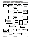
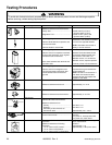
Testing Procedures
!
WARNI NG
To avoid risk of electrical shock, personal injury or death; disconnect power to oven and discharge capacitor
before servicing, unless testing requires power.
©2004 Maytag Services 16023293 Rev. 0
21
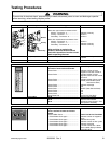
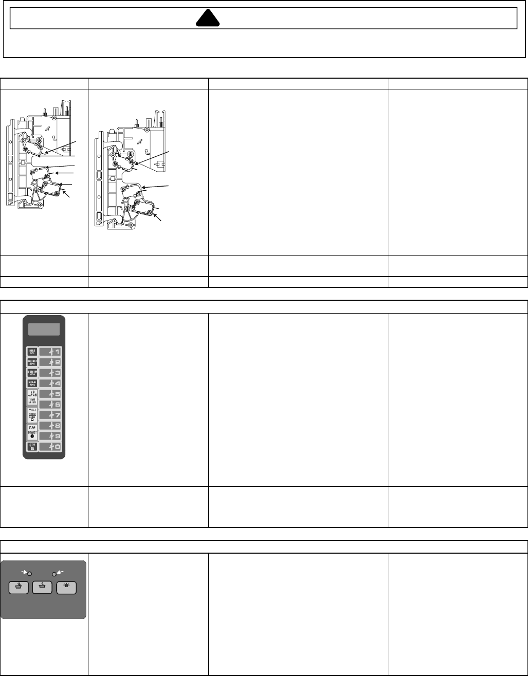
Illustration Component Testing Results
1
2
3
4
5
6
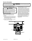
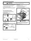
Interlock switch assembly
Primary
Monitor
Secondary
Disconnect wires to switch.
With door open measure resistance from:
Monitor - Terminal 3 - 4..........................
Primary - Terminal 1 - 2.........................
Secondary - Terminal 5 - 6.....................
With door closed measure resistance from:
Monitor - Terminal 3 - 4..........................
Primary - Terminal 1 - 2.........................
Secondary - Terminal 5 - 6.....................
After verifying or replacing the
module, reconnect wires to switch
and check operation of monitor circuit
before operating the oven.
Indicates continuity
Infinite
Ω
Infinite
Ω
Infinite
Ω
Indicates continuity
Indicates continuity
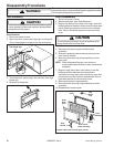
Lamp receptacle Test continuity of receptacle terminals. Indicates continuity with bulb
installed.
Wire Harness Test continuity of wires Indicates continuity
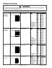
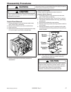
Electronic Control Panel
Service Test Mode: Open door, Press and Hold pad 3 for 5
seconds to enter service test mode.
Press Pad 1 ................................................
Press Pad 2 ................................................
Press Pad 3 ................................................
Press Pad 4 ................................................
Press Pad 5 ................................................
Press Pad 6 ................................................
Press Pad 7 ................................................
Press Pad 8 ................................................
Press Pad 9 ................................................
Press Pad 0 ................................................
Stop/Reset Pad...........................................
SERVICE appears in the display
Indicates number of hours
magnetron has been turned on
Indicates number of times
magnetron tube has been turned
on and off
Indicates number of door cycles
CLEAR (Press START pad to
reset service data.)
Indicates amperage
N/A
RESET (Clear Service Alarm)
N/A
N/A
N/A
Exit Service Test Mode
Error codes: E-08 ............................................................
E-09 ............................................................
E-10 ............................................................
Replace Control Board
Replace Control Board
Shorted or Open Keypad – Test
and replace if necessary
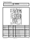
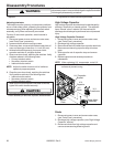
Electronic Dial Control Panel
START
DEFROST
50%70%
Hidden
Pad 1
Hidden
Pad 2
Service Test Mode: Open door, Press and Hold Hidden Pad
2 for 5 seconds to enter service test
mode.
Press Hidden Pad 2 ....................................
Press Hidden Pad 2 again .........................
Press Hidden Pad 2 again .........................
Press Hidden Pad 2 again .........................
Press Hidden Pad 2 again .........................
Press Hidden Pad 2 again .........................
Enters into Service Test Mode
Indicates number of magnetron
hours
Indicates tube cycles
Indicates number of door cycles
Indicates amperage
Turn dial to Clear Info – When
dial is rotated display indicates
CLEARED INFO