18P/N60254September28,2012
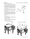
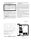
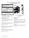
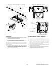
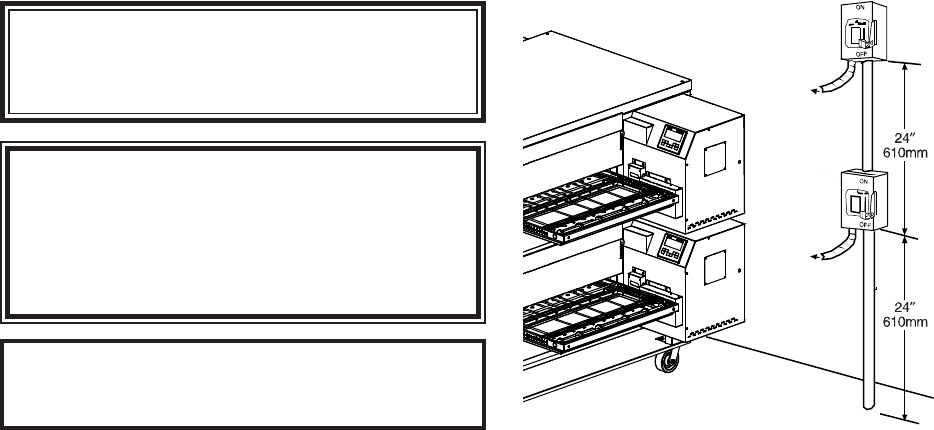
UTILITY ROUGH-IN DIMENSIONS AND POSITIONING
FOR PS740-SERIES OVENS
Figure 2-19. Typical PS740-Series Oven(s)
Installation
To Oven
To Oven
WARNING
DO NOT USE CONDUIT FOR GROUND
CONNECTION.
CAUTION
IT IS RECOMMENDED THAT THE OVEN
BE PLACED UNDER A VENTILATION
HOOD FOR ADEQUATE AIR SUPPLY
AND VENTILATION.
ELECTRIC SUPPLY TO BE
PROVIDED BY CUSTOMER
CIRCUIT BREAKER
Separate circuit breaker with lockout/tagout electrical shutoff
for each oven. Wire each oven separately.
100 Amp circuit breaker for 208-240V, or 50 Amp circuit
breaker for 380-480V.
ELECTRICAL SPECIFICATIONS
DOMESTIC: 208V main blower motors and elements,
3 Ph, 75 Amp draw, 50/60 Hz, 208-240V control circuit,
3 pole, 4 wire system per oven (3 hot, 1 grd).
Do NOT use conduit for ground.
or
DOMESTIC: 240V main blower motors and elements,
3 Ph, 65 Amp draw, 50/60 Hz, 208-240V control circuit,
3 pole, 4 wire system per oven (3 hot, 1 grd).
Do NOT use conduit for ground.
or
EXPORT: 380V elements, 3 Ph, 41 Amp draw, 50/60 Hz,
208-240V control circuit and main blower motor, 4 pole,
5 wire system per oven (3 hot, 1 neutral, 1 grd).
Do NOT use conduit for ground.
or
DOMESTIC: 480V elements, 3 Ph, 32.5 Amp draw,
50/60 Hz, 208-240V control circuit and main blower motor,
4 pole, 5 wire system per oven (3 hot, 1 neutral, 1 grd).
Do NOT use conduit for ground.
ELECTRICAL RATING
27.0 kW/hr.
SUPPLY WIRE
Supply wire size must be in accordance with the National
Electrical Code (current edition) and must be in compliance
with local codes.
NOTE: The electrical terminal connection marked “MP” located
inside the control compartment is desiganated for the blue
(neutral) wire to the oven. See the electrical wiring/schematics
in Section 6 of this manual.
SUGGESTED
If space permits, service should be located near the control
console end of the oven(s) to allow convenient access to
safety switches.
Suggested dimensions are shown; utility code
requirements supersede any factors shown.


