


THE TOTAL SMOKE PIPE LENGTH SHOULD NOT EXCEED 40% OF THE CHIMNEY HEIGHT ABOVE THE
STOVE TO A MAXIMUM HORIZONTAL RUN OF 10 FEET.
All smoke pipe must slope upwards at a minimum of 1/4" per foot (6 mm/0.3m) and all connections must be tight
and secured by three sheet metal screws equally spaced.
An uninsulated smoke pipe shall not pass through an attic, roof space, closet or similar concealed space, or
through a floor, ceiling, wall or partition, or any combustible construction.
Chimney specifications
If the chimney is ‘cold’, the normal combustion cycle will not work. A cold chimney may be caused by disuse, being too
large, not insulated, being external or not high enough. Exterior chimneys cool rapidly, causing poor draft and
condensation.
Chimney connector
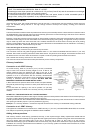
The stove should be located as close as possible to the chimney to avoid draft problems. Horizontal flue connectors restrict
the establishment of the required chimney draft and thereby prevent the normal functioning of the stove. Ensure that the
connection is supported and fastened to the stove.
Example : Screw the connector to the flue collar or wrap plumber’s strapping around the vertical section of the connector
and screw to either edge of the rear heat shield. Ensure that the strapping is snug fitting. A single wall chimney connector
may be used only within the room where the unit is located, between the oil stove and the chimney but never passing
through a combustible ceiling or wall. Minimum connector clearances to combustibles are to be maintained. If necessary,
where local codes allow, a wall thimble may be used.
There are two types of chimney connectors :
A single wall chimney connector may be used for top connexion :
This connector must be 316 grade 26 gauge stainless steel or 1 mm vitreous enamelled steel and with a 5" (127 mm)
diameter. Secure the connector joints with 3 sheet metal screws. The joints are to be airtight. All connector sections must
be attached to the unit and to each other with the crimped or male end pointing down towards the oil stove.
Use a double wall chimney connector for rear connexion :
The connector should be of the same make (manufacturer) as the chimney components
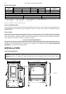
Chimney installation
Connection to a A-VENT chimney
An A-Vent chimney, either 4" (101,6 mm.) or 5" (127 mm.) in diameter
may be used. The minimum chimney height is to be 15 feet or 4.6
metres measured from the appliance flue collar to the top of the
chimney but not including any chimney caps. Installation of all chimney
systems is to be in accordance with the chimney manufacturers
installation instructions. If the stove is to be connected to a masonry
chimney, a stainless steel liner is required. DO NOT USE ANY
MAKESHIFT MATERIALS DURING INSTALLATION.
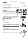
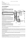
1. Move the stove into position with the flue centred, mid point between
two joists to prevent having to cut them. Use a plumb bob to line up the
centre.
2. Cut and frame an opening in the roof to provide a 2" (50 mm)
clearance between the outside of the chimney and any combustible
material.
DO NOT FILL THIS SPACE WITH ANY TYPE OF MATERIAL.
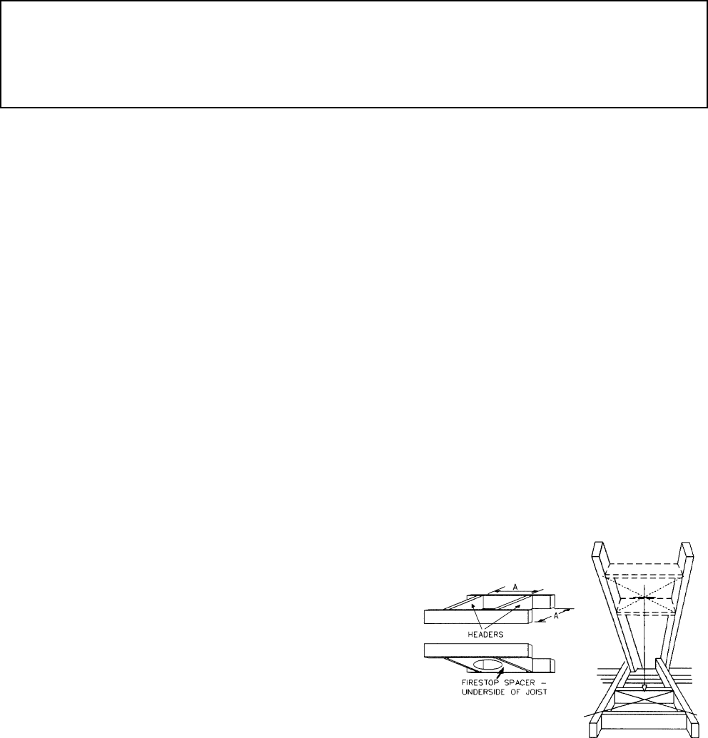
Nail headers between the joists for extra support. Firestopspacers must beplaced on thebottom of eachframed opening in
any floor or ceiling that the chimney passes through (figure 3).
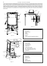
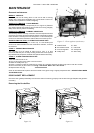
3. Hold a plumb bob from the underside of the roof to determine where the opening in the roof should be. Cut and frame the
roof opening to maintain proper 2" (50 mm) clearances (figure 4).
Example : A = Chimney diameter + 2 times the required clearance from chimney to combustible framing materials.
Connection to a L-VENT chimney
This appliance is certified to be connected to a L-VENT chimney, 5" (127 mm). Use NAPOLEON ADAPTOR, W 175-0198.
This adaptor is specifically designed for ENERGY VENT CHIMNEY.
Adding chimney sections
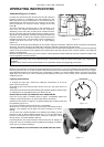
Add chimney sections, twist locking (clockwise) securely, to the required height. Safety requirements dictate that the
chimney must be at least 3 feet (915 mm) higher than the highest point where it passes through the roof and at least 2 feet
(610 mm) higher than the highest part of the roof or structure that is within 10 feet (3.05 m) of the chimney,
measured horizontally (figure 5). Obstacles close to the chimney may cause down drafts which may be prevented by the
installation of a chimney cap fitted with a wind deflector. If your chimney system is enclosed within the attic area, a rafter
radiation shield is required.
Document n° 1092-1 EN ~ 04/02/2002
6
Figure 3
Figure 4