24
Repair
Service Manual EF 473 / EF 474 enVersion 1.0
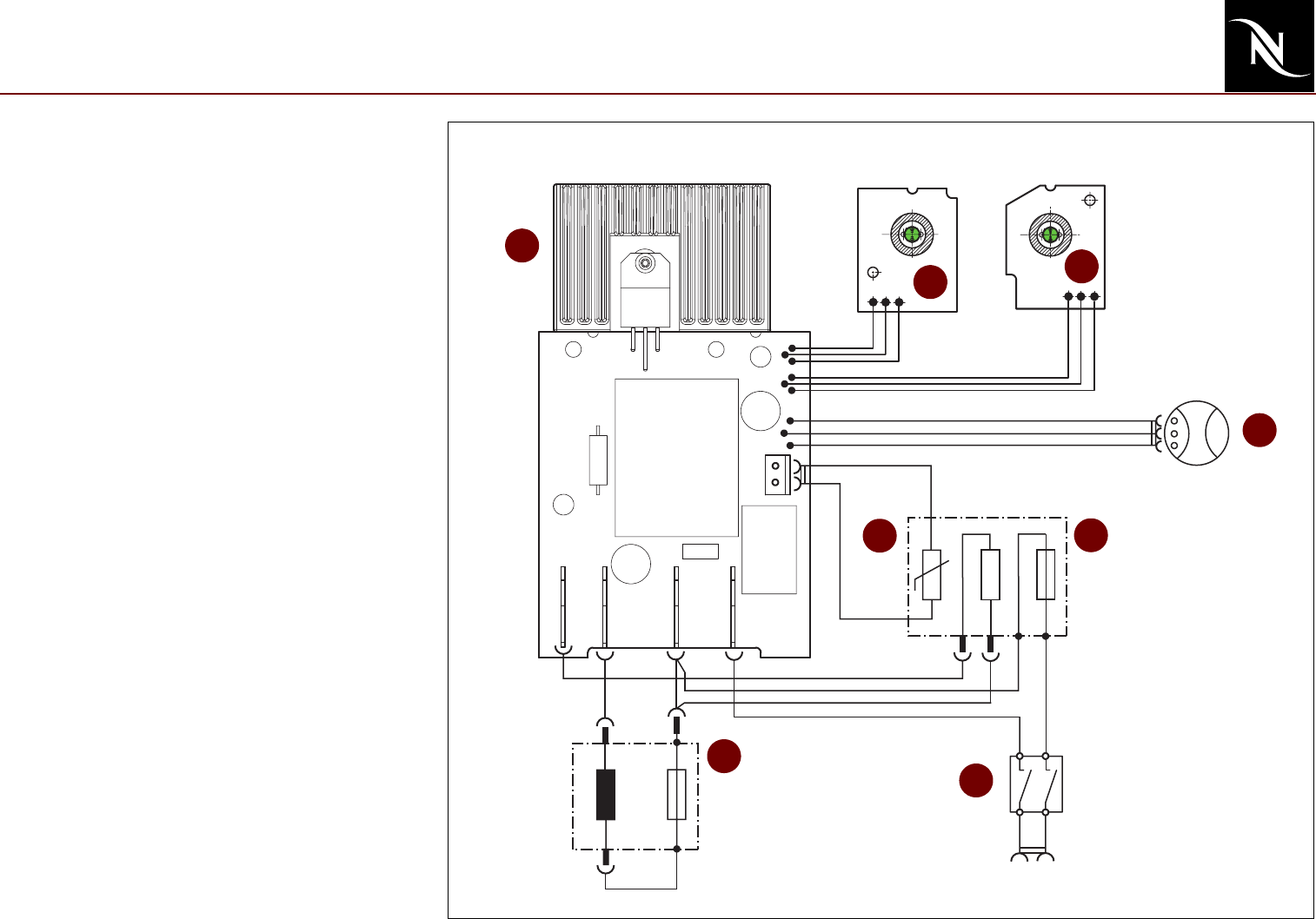
Electronic control board, wiring
diagram - USA (UL, 120 V / 60 Hz)
1) Heat sink
2) Print for button "large cup" with LED
3) Print for button "small cup" with LED
4) Flow meter
5) NTC temperature sensor
6) Fine-wire fuse on thermoblock
7) On/Off switch
8) Fine-wire fuse on pump
5
Electronic Main Board
NTC
Thermoblock
T 167°C
Pump
T 128°C
Mains Plug
Heat
Pump
Flow meter
Print “large cup”
Print “small cup”
Neutral
Line
L
N
On/Off switch
1
2
1a
2a
1
5
4
2
3
7
6
8


