


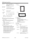
Pin assignments
Signal
pin
Return
pin Signal Direction Description
119STROBE IN
STROBE
pulse to read
data.
2
3
4
5
6
7
8
9
20
21
22
23
24
25
26
27
DATA 1
DATA 2
DATA 3
DATA 4
DATA 5
DATA 6
DATA 7
DATA 8
IN
IN
IN
IN
IN
IN
IN
IN
These signals represent
information in bits 0 to 7 of
parallel data respectively.
Each signal is at HIGH level
when data is logical 1 and
LOW when it is logical 0.
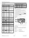
10 28 ACKNLG OUT
About a 5-
µ
s pulse. LOW
indicates data has been
received and the printer is
ready to accept more data.
11 29 BUSY OUT
A HIGH signal indicates the
printer cannot receive data.
The signal goes HIGH in the
following cases:
1) During data entry
(for each character)
2) During initialization
3) During self test and
default-setting printing
4) During a printer-error
state
12 30 PE OUT
A HIGH signal indicates the
printer is in a paper-out
state or in an error state
13 - SLCT OUT
Pulled up to +5 V through
1 k
Ω
resistance
14 - AUTO
FEED
XT
IN
When this signal is LOW,
the paper is automatically
fed one line after printing
15 - NC -
Not used
16 - GND -
Logic ground level
17 - CHASSIS
GND
-
Printer’s chassis ground,
which is connected to the
logic ground
18 - NC -
Not used
19-30 - GND -
Twisted-pair return signal
ground level
31 16 INIT IN
When this signal goes LOW,
the printer controller is reset
to its state when the power
is first turned on and the
print buffer is cleared. This
level is normally HIGH; its
pulse width must be more
than 50
µ
s at the receiving
terminal.
32 - ERROR OUT
This signal level goes LOW
when the printer:
1) Is out of paper
2) Is in an error state
3) Has no ink cartridges
installed
Signal
pin
Return
pin Signal Direction Description
33 - GND -
Same as for pins 19-30
34 - NC -
Not used
35 - +5 V OUT
Pulled up to +5 V through
1 K
Ω
resistance
36 - NC -
Not used
Notes:
❏ The column heading “Direction” refers to the direction of signal
flow as viewed from the printer.
❏ “Return pin” denotes the twisted-pair return pin to be
connected at signal ground level. For the interface wiring, be
sure to use a twisted-pair cable for each signal and to complete
the connection on the return side.
❏ All interface conditions are based on TTL level. Both the rise
and fall times of each signal must be less than 0.2 microseconds.
❏ Data transfer must be carried out by observing the
ACKNLG or
BUSY signal. Data transfer to this printer can be carried out
only after receipt of the ACKNLG signal or when the level of the
BUSY signal is LOW.
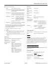
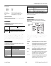
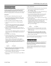
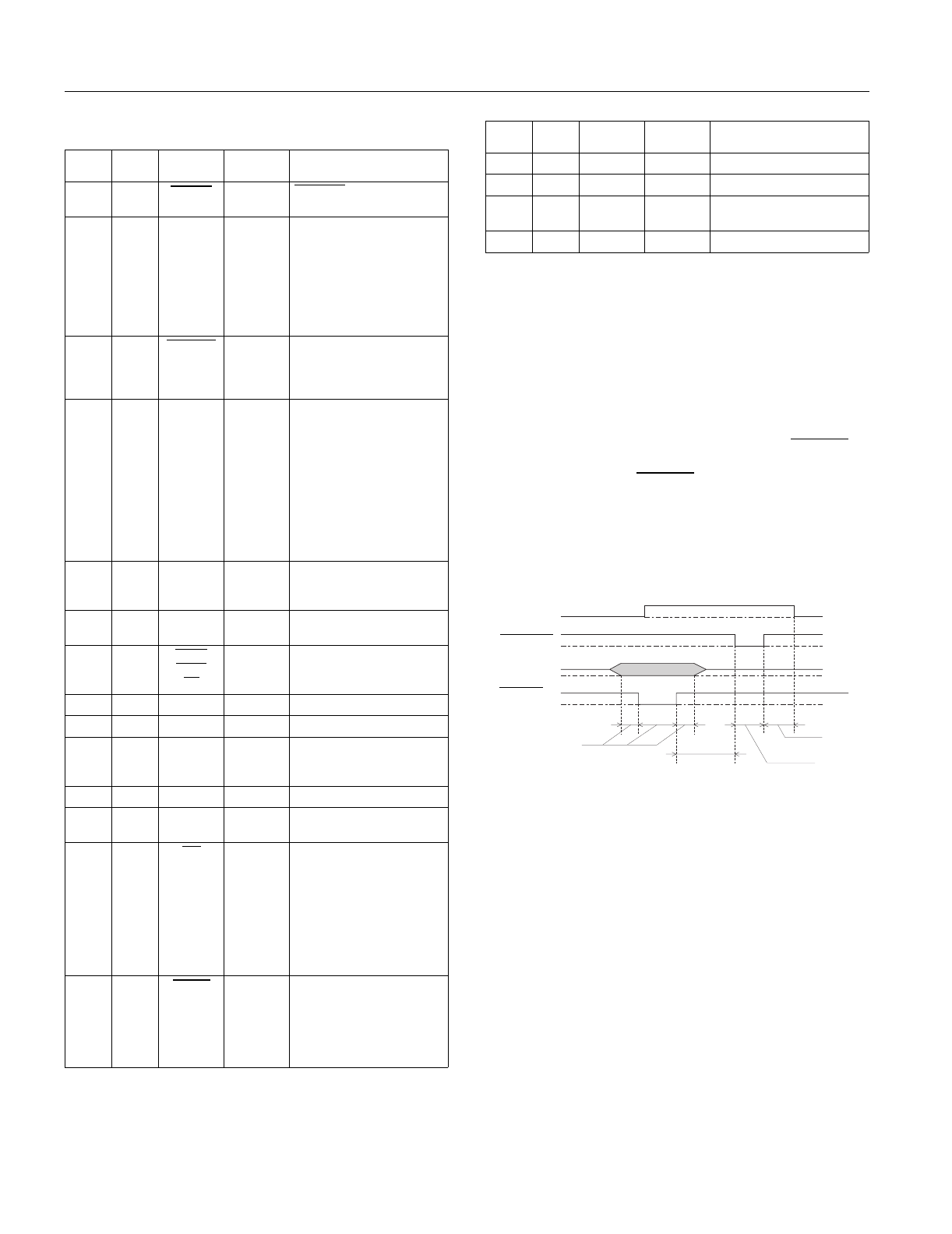
Timing chart
The figure below shows the timing chart for the parallel
interface.
Transition time (both the rise and the fall) of every signal must be less
than 0.2
µ
s.
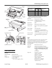
Serial Interface
The printer’s built-in serial interface is based on the RS-422
standard to allow the printer to be connected to an Apple
Macintosh.
Standard: Based on RS-422
Synchronization: Asynchronous
Bit rate: 57.6 Kbps/230.4 Kbps
Handshaking: DTR and XON/XOFF protocol
BUSY
DATA
0.5
µ
s (Min.)
0
µ
s (Min.)
5
µ
s (Typ.)
0
µ
s (Min.)
ACKNLG
STROBE
EPSON Stylus Pro and Pro XL
EPSON Stylus Pro and Pro XL-4 8/1/95 Ink Jet Printers