


PLANNING DUCTWORK AND WIRING
Ductwork
1. Use 4” round duct.
2. Plan to run duct from discharge opening of fan to the
outside. For best fan performance, make the duct run as
short as possible and use a minimum number of elbows.
3. Use optional ducting accessories as required.
Wiring
Plan to run 120vAC house wiring (with ground) from the
power source through a standard wall switch.
Preparation
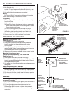
1. Refer to Figure 1. Remove blower/power unit assembly
from the housing.
(a) Unplug the power unit.
(b) Remove the screw (located next to plug-in receptacle)
which holds blower/power unit mounting plate in place.
Do not misplace this screw.
(c) Lift the mounting plate at the end near the plug-in
receptacle until blower wheel clears the scroll.
(d) Remove plate by pulling its tabs out of slots in the
housing. Set blower/power unit aside until needed.
2. Remove one of the wiring knockouts from housing.
MOUNTING THE HOUSING
Mounting Using Mounting Tabs
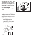
Refer to Figure 2.
1. Locate fan housing next to ceiling joist.
2. Using wood screws (not provided) loosely attach the
housing to ceiling joist through the keyhole slots in
mounting tabs.
3. Adjust housing so that it will be flush with the finished
ceiling. For the grille to fit properly, the housing’s rim must
not extend beyond finished ceiling surface.
4. When housing is properly adjusted, tighten screws in slots.
Mounting Using Hanger Bars
(hanger bars sold separately, order model HB4)
Refer to Figure 3.
1. Insert hanger bars in slots provided in housing.
2. Locate fan housing between joists so that the bottom of the
housing is even with the planned finished ceiling. Extend
the hanger bars to the joists.
3. Use screws or nails (not provided) to secure hanger bars to
ceiling joists.
INSTALLING DUCTWORK
1. Refer to Figure 2. Place duct collar over flanges at
discharge opening of fan. Secure collar by snapping tabs
into slots in flanges.
2. Run 4” round duct from outside to fan’s discharge opening.
3. Connect duct to fan’s duct collar.
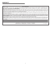
WIRING
All wiring must comply with local codes and unit must
be properly grounded.
1. Run 120vAC house wiring (with ground) from wall switch to
fan location.
2. Pull wire through access hole and into junction box.
3. Refer to Figure 4. Use approved wire nuts to connect
house supply wires to fixture as follows: white to white;
black to black. Connect green or bare ground wire to green
ground lead.
FIGURE 4
FIGURE 3
FIGURE 2
DUCT COLLAR
COLLIER DE GAINE
COLLARÍN DEL TUBO
WIRING KNOCKOUT
OUVERTURES
PRÉAMORCÉES
AGUJERO CIEGO DE
CABLEADO
MOUNTING TAB
PATTES DE MONTAGE
LENGÜETA DE MONTAJE
FLANGES
COLLERETTES
BRIDAS
GREEN GROUND
LEAD
VIS VERTE DE MISE À
LA TERRE
HILO VERDE DE
CONEXIÓN A TIERRA
STANDARD
WALL SWITCH
(NOT INCLUDED)
INTERRUPTEUR
MURAL STANDARD
(NON INCLUS)
INTERRUPTOR DE
PARED ESTÁNDAR
(NO SE INCLUYE)
FIELD GROUNDING WIRE
HANGER BARS
(SOLD SEPARATELY)
BARRES DE SUSPENSION
(VENDUES SÉPARÉMENT)
BARRAS DE SUSPENSIÓN
(SE VENDEN POR SEPARADO)
JUNCTION BOX
BOÎTE DE
JONCTION
CAJA DE
CONEXIONES
SWITCH BOX
BOÎTE D’INTERRUPTEUR
CAJA DEL INTERRUPTOR
120vAC, 60Hz HOUSE
POWER
COURANT DOMESTIQUE
120V CA, 60 Hz
ELECTRICIDAD DOMÉSTICA:
120 V CA, 60 Hz
FIL DE MISE À LA TERRE
HILO DE CONEXIÓN A TIERRA
2