WIRING
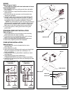
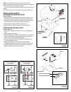
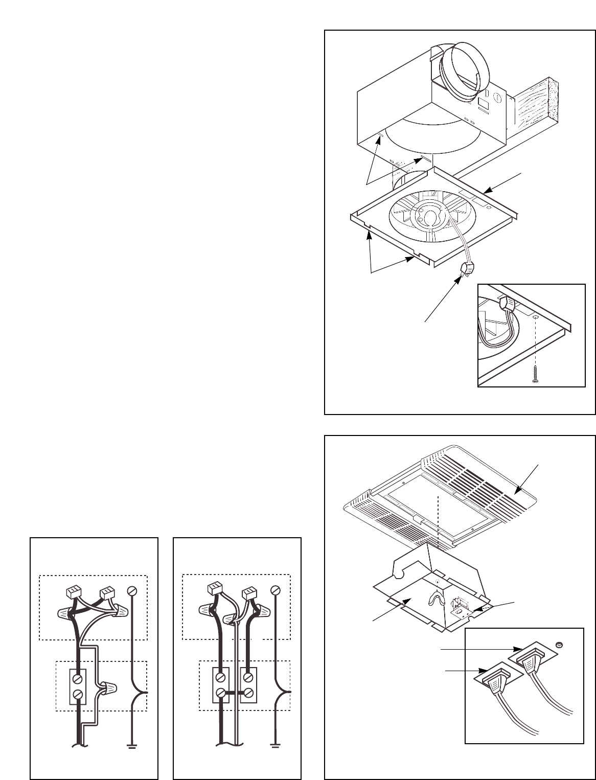
Refer to Figures 5 and 6.
All wiring must comply with local codes and unit must
be properly grounded.
1. Run 120vAC house wiring (with ground) from wall switch
to fan location.
2. Insert and secure an approved box connector into wiring
entrance hole.
3. Pull wires through box connector and into junction box.
Tighten box connector.
4. If a single switch will be used to control both the fan and
the light, make wiring connections as shown in Figure 5.
If a double switch will be used for separate control of the
fan and light, make connections as shown in Figure 6.
NOTE: If a double switch is used, the wiring connections
determine which receptacle will b e used for the fan motor
plug and which receptacle will be used for the light plug.
Make note of this when making the wiring connections.
5. Connect the green (or bare) ground wire to the green
ground lead.
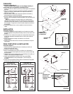
POWER/BLOWER UNIT INSTALLATION
Refer to Figure 7.
1. Place power/blower unit into housing so that mounting
plate's tabs insert into slots in housing.
2. Press other end of mounting plate down until it is firmly
seated over scroll and plug-in receptacles.
3. Secure mounting plate to housing with provided screw.
4. Insert motor plug into junction box receptacle.
COMPLETING INSTALLATION
Refer to Figure 8.
1. Remove wing nut from the threaded bolt on motor
mounting strap.
2. Place reflector into grille.
3. Align grille/reflector assembly with housing and insert light
plug into receptacle in junction box. (See figure 1 for
correct orientation)
4. Using wing nut, secure grille/reflector assembly to motor
mounting strap.
5. Install 26W fluorescent lamp (NEMA type
CFM26W/GX24D/827) into socket. (Lamp not provided)
6. Install lens by squeezing both sides and inserting lens tabs
into slots in grille.
FIGURE 6
FIGURE 7
FIGURE 5
FIGURE 8
SINGLE SWITCH
CONTROL
DOUBLE SWITCH
CONTROL
WHITE
WHITE
BLACK
120vAC
GROUND
GROUND
120vAC
BLACK
BLACK
SLOTS
MOUNTING
PLATE
MOTOR PLUG
INSERT TABS
INTO SLOTS
GRILLE
LAMP SOCKET
REFLECTOR
LIGHT PLUG
FAN PLUG


