


PRECAUCION
1. Solamente para uso general de ventilación. No utilice
para descargar materiales o vapores riesgosos o
explosivos.
2. Para evitar daños al motor y evitar que las navajas del
abanico emitan mucho ruido o estén fuera de balance,
mantenga el motor libre de pelusa, polvo, etc.
3. Si usa un termóstato con este producto, el abanico puede
arrancar automáticamente. Para reducir el riesgo de
lesiones, apague la fuerza eléctrica en el panel de
servicio y cierre con llave el panel de servicio para evitar
que alguien prenda la fuerza eléctrica accidentalmente.
4. El motor de su extractor tiene dispositivo de sobrecarga
térmica, al cual automáticamente apagará el motor si se
sobrecalienta. El motor funcionará de nuevo cuando se
enfríe. Si el motor continua apagándose y arrancando,
hágalo componer.
5. Por favor lea la etiqueta con las especificaciones del
equipo para otros requisitos y mayor información.
2
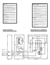
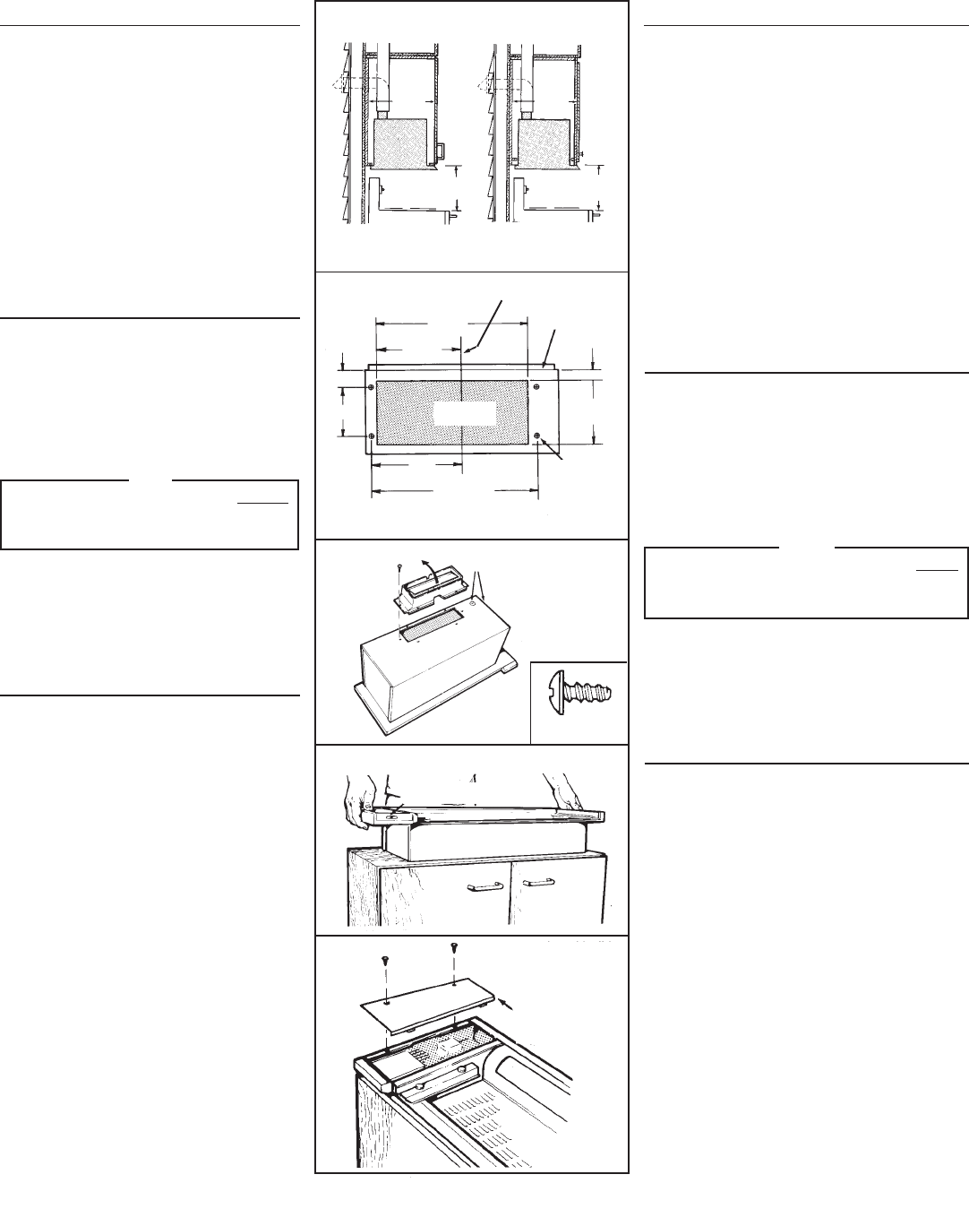
FIG. 3
FIG. 4
FIG. 1
FLUSH BOTTOM CABINET
GABINETE CON FONDO A RAS
FIG. 2
CABINET BOTTOM VIEW
VISTA DESDE LA PARTE
INFERIOR DEL GABINETE
CABINET FRONT
FRENTE DEL
GABINETE
CABINET CENTER LINE
LINEA CENTRAL DEL GABINETE
0,95 CM DIA.
CLEARANCE
HOLES
AGUJEROS DEL
CLARO
ELECTRICAL KNOCKOUTS
PLACAS DE QUITAR GOLPEANDO
FIG. 5
ACCESS COVER
TAPA DE ACCESO
RECESSED BOTTOM CABINET
GABINETE CON FONDO AHUECADO
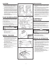
PLANIFIQUE LA
INSTALACION
Su nuevo extractor cabrá en la parte inferior de un gabinete
estándar de 76,2 cm con la parte inferior a ras o ahuecada,
con o sin marco, que tenga una profundidad mínima de
27,94 cm desde la parte frontal hacia a la pared.
El ducto de la unidad sube verticalmente. A un ducto hori-
zontal se lo puede instalar como se muestra.
Para operación segura, el extractor ya montado tiene que estar
a un mínimo de 45,72 cm sobre la superficie de la cocina.
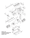
Para una instalación más fácil, al extractor debe de
instalárselo en el gabinete antes de montar el gabinete en
la pared.
NOTESE
QUITE EL CAJÓN DE VIDRIO DE LA UNIDAD
ANTES
DE INSTALAR EL EXTRACTOR EN EL GABINETE
PARA EVITAR DAÑAR EL CAJÓN. VÉASE PASO 13
EN PÁGINA 3.
A este extractor se lo puede instalar fácilmente siguiendo
estos pasos básicos:
• Marque y corte el hueco en la parte inferior del gabinete.
• Sujete el extractor al gabinete.
• Monte el gabinete sobre la pared.
• Conecte los ductos y el cableado. (FIG. 1)
INSTALE EL EXTRACTOR
1.
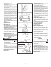
Marque y corte el hueco en la parte inferior del gabinete.
(FIG. 2)
Prepare la parte inferior del gabinete como se muestra
en Fig. 2. Asegúrese que localice el hueco y los cuatro
agujeros desde la parte frontal del gabinete para
asegurarse que se monte a ras.
2. Sujete el conector para el regulador/ducto. (FIG. 3)
Use dos (2) tornillos (suministrados) para sujetar el
conector al bastidor. La placa del regulador debe de
abrirse en la dirección de la flecha.
3. Quite la placa de quitar golpeando.
Escoja, ya sea la parte superior, o parte lateral del
bastidor para la entrada de cable eléctrico. Quite la placa
de quitar golpeando apropiada.
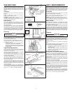
4. Ponga el bastidor dentro del hueco. (FIG. 4)
Con cuidado meta el bastidor dentro del hueco del
gabinete con el control de deslizar hacia en frente.
5. Quite la tapa de acceso. (FIG. 5)
"
"
24-1/2"
62,23 CM
13-1/2"
34,29 CM
2-5/8"
6,67 CM
7"
17,78 CM
14"
35,56 CM
25-5/8"
65,09 CM
9-1/2"
24,13 CM
1-5/8"
4,13 CM
(4) 3/8" DIA.
18" MIN.
45,72 CM MIN.
11 "
27,94 CM
MIN.
(INSIDE)
(ADENTRO)
18" MIN.
45,72 CM MIN.
11"
27,94 CM
MIN.
(INSIDE)
(ADENTRO)
CUT-OUT
HUECO
#8-18 x 3/8"
SLIDE CONTROL
CONTROL DE DESLIZAR
CAUTION
1. For general ventilating use only. Do not use to exhaust
hazardous or explosive materials and vapors.
2. To avoid motor bearing damage and noisy and/
or unbalanced impellers, keep drywall spray,
construction dust, etc. off power unit.
3. When using a thermostat with this product, fan may
start automatically. To reduce the risk of injury, switch
power off at service panel and lock service panel to
prevent power from being switched on accidentally.
4. Your hood motor has a thermal overload which will
automatically shut off the motor if it becomes
overheated. The motor will restart when it cools
down. If the motor continues to shut off and restart,
have the hood serviced.
5. Please read specification label on product for further
information and requirements.
PLAN THE INSTALLATION
Your new hood will fit a standard 30" wide flush bot-
tom or recessed bottom, framed or frameless kitchen
cabinet which has a minimum depth of 11" from face
to inside of back wall.
The unit is ducted vertically. Horizontal ducting can
be accomplished as shown.
For safe operation, the mounted hood must be a mini-
mum of 18" above the cooking surface.
For easiest installation, range hood should be installed
in cabinet before mounting cabinet to wall.
NOTE
REMOVE GLASS DRAWER FROM UNIT
BEFORE
INSTALLING HOOD IN CABINET TO PROTECT
DRAWER FROM DAMAGE. SEE STEP 13 ON
PAGE 3.
This hood can easily be installed by following these
basic steps:
• Mark and cut out cabinet bottom.
• Secure hood to cabinet.
• Mount cabinet on wall.
• Connect ductwork and power cable. (FIG. 1)
INSTALL THE HOOD
1. Mark and cut-out cabinet bottom. (FIG. 2)
Prepare the cabinet bottom as shown in Figure 2.
Be sure to locate the cut-out and four holes from
the front of the cabinet to assure a flush mount.
2. Attach damper/duct connector. (FIG. 3)
Use two (2) screws (provided) to attach connec-
tor to housing. Damper flap should open in direc-
tion indicated by arrow.
3. Remove electrical knockout.
Choose either the top or side of housing for elec-
trical cable entrance. Remove the appropriate
knockout.
4. Set housing into opening. (FIG. 4)
Carefully lower housing into cabinet opening with
slide control to the front.
5. Remove access cover. (FIG. 5)