


INSTALLATION IN
A NEW CONSTRUCTION SITE
PREPARATION
CAUTION: When handling the power unit do not reach in
the end openings and bend the blower wheels.
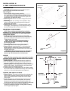
Refer to Figure 1.
1. Remove power unit from housing assembly.
(a) If necessary, unplug power plug from mating connector.
(b) Loosen wing nut on hanger rods that hold the power unit.
(c) Unfasten hanger rods from slots and remove power unit.
(d) Set power unit aside until needed.
2. Refer to Figure 2. Remove one of the wiring knockouts from
the housing.
3. Refer to Figure 2. The ventilators can be ducted for either
vertical or horizontal discharge. Determine the method of
discharge that will be used.
4. Refer to Figure 3. Mount 3
1
⁄
4
" x 10" damper section on top
of housing for vertical discharge or on the side of housing for
horizontal discharge with two (2) screws furnished.
MOUNTING THE HOUSING
NOTE: These ventilators are designed for installation
between 16" O.C. ceiling joists with no framing necessary.
If the building structure has 24" O.C. joists construction,
framing will be required.
1. Position housing between ceiling joists and adjust height
to finished ceiling. Loosen two (2) hex nuts for each mounting
bracket from inside the housing and make the adjustment.
Tighten the four (4) hex nuts.
NOTE: There are four (4) extra mounting slots in
the housing long sides for mounting or relocating
the mounting brackets.
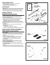
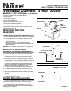
2. Refer to Figure 4. Screw housing to joists using holes
in mounting brackets and four (4) screws furnished.
3. Refer to Figure 2. Install standard 3
1
⁄
4
" x 10" ductwork from
damper section to outside wall or through roof and mount
appropriate wall or roof cap (optional.) Refer to the instructions
provided with the caps.
IMPORTANT: Be certain there are not any obstructions
at the discharge of the ventilator. Be certain insulation
does not get into the ductwork or into the blower.
WIRING
NOTE: All wiring connections must comply with local codes,
ordinances and the National Electrical Code and the ventilator
must be properly grounded.
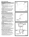
1. Refer to Figure 5. Loosen screws and remove junction box.
2. Run 120vAC supply wiring with ground through switch box to
knockout in ventilator housing and secure with box connector.
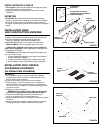
3. Refer to Figure 6. Connect supply wires to ventilator wires: black
to black, white to white. Connect ground to green ground lead.
4. Replace junction box and tighten screws.
5. Connect supply wire to a listed general use wall switch in switch
box of use a listed timer suitable for the voltage and current rating
of the fan or a listed solid-state speed control (optional.)
POWER UNIT INSTALLATION
1. Refer to Figure 7. The power unit mounts with two hanger rods
to the mounting brackets. Insert the hanger rods through the
holes in the mounting bracket hooking them from the inside
to the outside.
2. Position the power unit so that its discharge opening is in line
with the installed ductwork. Hold the power unit in position
between the mounting brackets and swing the hanger rods
into the slots on the power unit and securely tighten the wing nuts.
3. Plug the three (3) wire connector from the junction box
into the wire receptacle connector from the power unit making
sure the plug is properly aligned.
FIGURE 4
FIGURE 5
FIGURE 6
MOUNTING
BRACKET
VENTILATOR
HOUSING
JUNCTION
BOX
GREEN
GREEN
GROUND
SCREW
WHITE
SWITCH
BOX
120vAC, 60 Hz
HOUSE POWER
STANDARD
WALL SWITCH
EARTH
GROUND
BLACK