ERROR
CODE
(SYMPTOM)
POSSIBLE CAUSE AND REMEDY
GROUP
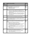
F01 + beep
Temperature in the exhaust duct raised above 260 F due to
a) Fire in the cavity
b) Clogged air filter (not applicable to OCS models)
c) Obstruction of the exhaust duct
d) Shorted temperature sensor
OCS
PRO-1
PRO-2
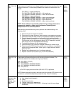
F03 or F04
Mismatch between the incoming line voltage and the voltage setting of the oven.
a) Make sure the line voltage corresponds with the setting of the oven. The
voltage selector is located at the back and consists of two plugs. The white
plug sets the oven for 208 V and black plug (or white plug with a black dot)
sets the oven for 230 V.
b) Make sure the line voltage is within +/- 10% tolerance. This is especially
important during summer months, where line voltage has tendency to drop.
c) If both steps above check OK, the error(s) may be caused by defective
controller (DPU) board
PRO-1
PRO-2
F05
Internal memory failure has occurred. Replace the controller (DPU) board
PRO-1
F09
Oven that was designed for 50Hz electricity is attempted to operate in the 60Hz
environment. If the model number of the oven in question is listed above, most likely
the controller (DPU) board has failed.
PRO-1
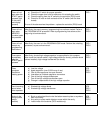
F33 or F34
These codes may be triggered by either excessive heat within the oven or poor
grounding of either the temp sensor or the controller (DPU) board. Check the
following:
a) Clogged air filter (not applicable to OCS models)
b) Obstruction of the exhaust duct or insufficient ventilation
c) Defective thermal sensor (should read 30 – 70 kohm in room temperature)
d) Grounding of the thermal sensor (possible oxidation)
e) Poor connection (oxidation) at CN4 connector (PRO-1 models only)
f) Poor or no ground at the controller (DPU) board – ensure that all screws
securing the board are in place
g) Missing screw(s) that secure the escutcheon to the frame (OCS models
only)
h) If all steps above check OK, the error(s) may be caused by defective
controller (DPU) board
OCS
PRO-1
PRO-2
F44
This code will appear if there is malfunction of the keypad. Check:
a) Ribbon connector of the keypad for conductive residue or oxidation
b) Perform continuity test of the keypad (use matrix shown in the service
manual - DPU circuit diagram)
c) Replace the keypad, if both steps prove to be inconclusive
PRO-1
PRO-2


