


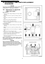
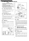
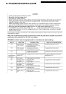
19.1. High voltage transformer
1. Remove connections from the transformer terminals and
check continuity.
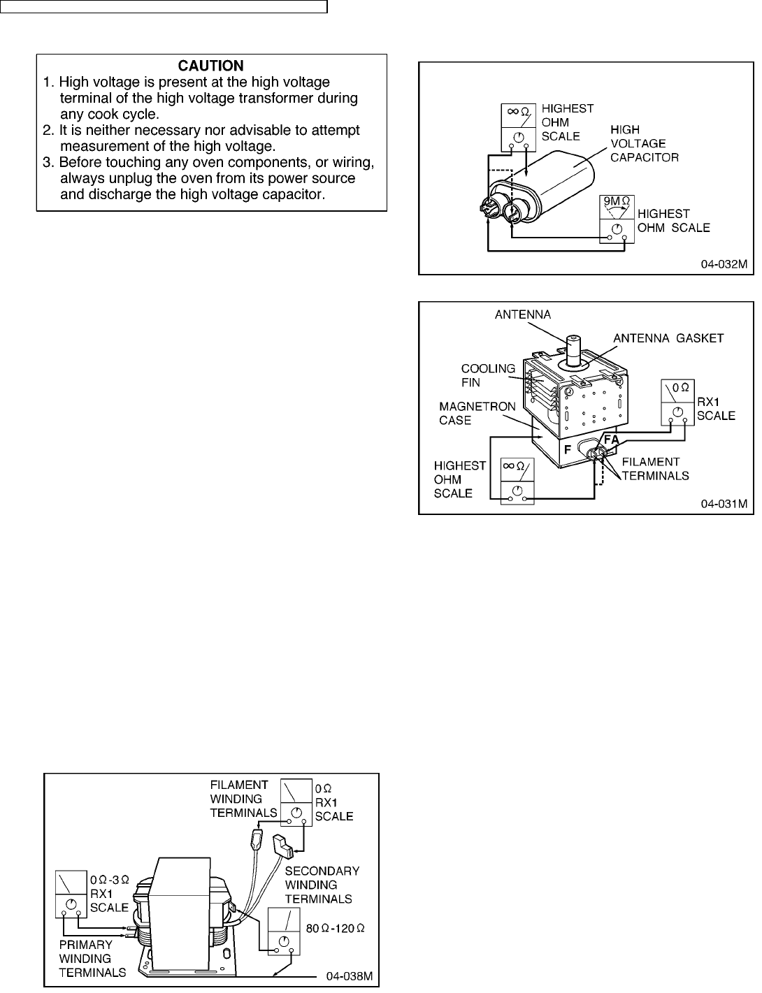
2. Normal (cold) resistance readings should be as follows:
Secondary winding Approx. 80Ω—120Ω
Filament winding Approx. 0Ω
Primary winding Approx. 0Ω—3Ω
19.2. High voltage capacitor
1. Check continuity of capacitor with meter on highest OHM
scale.
2. A normal capacitor will show continuity for a short time, and
then indicate 9MΩ once the capacitor is charged.
3. A shorted capacitor will show continuous continuity.
4. An open capacitor will show constant 9MΩ.
5. Resistance between each terminal and chassis should be
infinite.
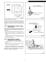
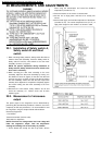
19.3. Magnetron
Continuity checks can only indicate an open filament or a
shorted magnetron. To diagnose for an open filament or
shorted magnetron.
1. Isolate magnetron from the circuit by disconnecting the
leads.
2. A continuity check across magnetron filament terminals
should indicate one ohm or less.
3. A continuity check between each filament terminal and
magnetron case should read open.
19.4. Diode
1. Isolate the diode from the circuit by disconnecting the leads.
2. With the ohmmeter set on the highest resistance scale,
measure the resistance across the diode terminals.
Reverse the meter leads and again observe the resistance
reading. Meter with 6V, 9V or higher voltage batteries
should be used to check the front-to-back resistance of the
diode, otherwise an infinite resistance may be read in both
directions.
A normal diode's resistance will be infinite in one direction
and several hundred kΩ in the other direction.
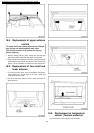
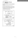
19.5. Membrane key board
(Membrane switch assembly)
Check continuity between switch terminals, by tapping an
appropriate pad on the key board. The contacts assignment of
the respective pads on the key board is as shown in digital
programmer circuit.
19.6. Protector diode
1. Isolate the protector diode assembly from the circuit by
disconnecting its leads.
2. With the ohmmeter set on the highest resistance scale,
measure the resistance across the protector diode
terminals.
Reverse the meter leads and again observe the resistance
reading. A normal protector diode's resistance will be
infinite in both directions. It is faulty if it shows continuity in
19 COMPONENT TEST PROCEDURE
30
NE-1257R/NE-1257CR / NE-1757R/NE-1757CR / NE-2157R/NE-2157CR / NE-1258R