9
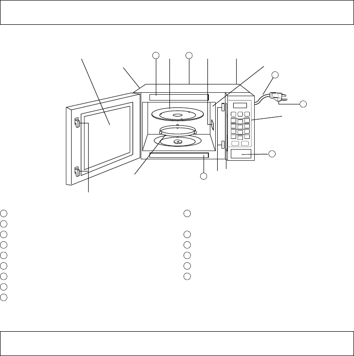
Oven Components Diagram
Control Panel
1
External Air Vent
2
Internal Air Vent
3
Door Safety Lock System
4
Exhaust Air Vent
5
Control Panel
6
Identifi cation Plate
7
Glass Tray
8
Roller Ring
9
Heat/Vapor Barrier Film
(do not remove)
10
Waveguide Cover
(do not remove)
11
Door Release Button
12
Warning label
13
Menu label
14
Power Supply Cord
15
Power Supply Plug
11
12
13
14
15
(1) Display Window
(2) Popcorn Pad (
page 14)
(3) Sensor Reheat Pad (
page 17)
(4) Sensor Cook Pad (
page 17)
(5) Power Level (10 Levels) Pad
(
page 13)
(6) Inverter Turbo Defrost Pad
(
page 15)
(7) Keep Warm Pad (
page 13)
(for NN-SN653S)
(8) Quick 30 or Quick 30 (more)
Pad (
page 13, 14)
(9) Number Pads
(10) Timer/Clock (More/Less) or
Timer/Clock (Less) Pad
(
page 11, 14, 20)
(11) Stop/Reset Pad
Before cooking: One tap clears memory.
During cooking: One tap temporarily stops
the cooking process. Another tap cancels
all your instructions and time of day or
colon appears in the Display Window.
(12) Start Pad
One tap allows oven to begin functioning.
If door is opened or Stop/Reset Pad is
pressed once during oven operation, Start
Pad must be pressed again to restart oven.
12


