


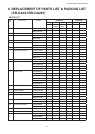

3
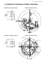
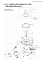
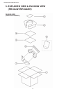
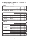
SR-GA421/SR-GA281/SR-GA721
L
N
MICA HEATER ASS’Y
CAST HEATER
LAMP RESIST
.
T.F.
INPUT
SWITCH
LAMP RESIST.
KEEP WARM NEON LAMP
(BIG)
(SMALL
)
E
Green
RICE COOKING NEON LAMP
Lamp Lead Wire A (Orange)
Lead Wire (Orange)
Lamp Lead Wire C (Brown)
Twist one time
Lamp Lead Wire B (Gray)
Lever Earth Lead Wire (Green)
Silicone Tube (Blue)
N
Twist two time
Thermal Fuse Wire (Gray)
Switch Lead Wire (Blue)
Cord Wire Earth (Green)
Silicone Tube (Green)
Silicone Tube (Brown)
Cord Bush
1
0
˚
±
5
˚
Thermal Fuse Wire (Brown)
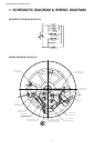
N
Cord Bush
Silicone Tube (Blue)
Silicone Tube (Brown)
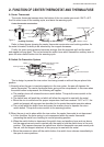
After ass’y, Mica Heater Ass’y must not overlie
the Outer Case of Center Thermostat
.
Water guard
Cord Wire Earth (Green)
Silicone Tube (Green)
Thermal Fuse Wire (Blue)
Lever Earth Lead Wire (Spiral Green)
Wiring Lead Wire (Brown
)
Lamp Lead Wire A (Red
)
Lamp Lead Wire C (Brown
)
Twist one time
Thermal Fuse Wire (Gray)
Lamp Lead Wire B (Gray)
After assembly Mica Heater case
Must no touch the terminal of cast heat
.
Glass tape 20 x 20 mm
.
After as
s’y, gap between terminal and mica heater case must be more than 4 mm.
1
0
˚
±
5
˚
Cast Heater
Lamp Resistor
Lamp Resistor
Switch
Keep Warm Neon Lamp
Rice Cooking Neon Lam
p
Gra
y
Input
Blue
Brown
N
L
E
Gree
n
Mica Heater Ass’y
T.F. T.F.
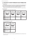
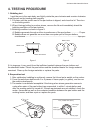
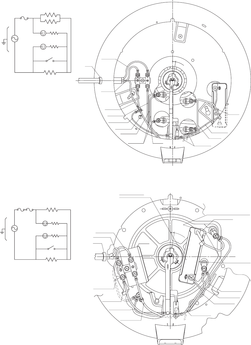
1. SCHEMATIC DIAGRAM & WIRING DIAGRAM
SCHEMATIC DIAGRAM (SR-GA421) WIRING DIAGRAM (SR-GA421)
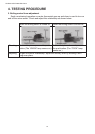
SCHEMATIC DIAGRAM
(SR-GA281) WIRING DIAGRAM (SR-GA281)